Left hand material microstrip antenna with branch shaped structure of X waveband

A microstrip antenna, left-handed material technology, applied in the direction of antenna, radiating element structure, electrical components, etc., can solve the problems of poor directivity, low gain, low radiation efficiency, etc.

Inactive Publication Date: 2009-01-14
NORTHWESTERN POLYTECHNICAL UNIV
View PDF0 Cites 14 Cited by
  • Summary
  • Abstract
  • Description
  • Claims
  • Application Information

AI Technical Summary

Problems solved by technology

[0004] The purpose of the present invention is to provide an X-band dendritic structure left-handed material microstrip antenna, ...

Method used


Image

  • Left hand material microstrip antenna with branch shaped structure of X waveband
  • Left hand material microstrip antenna with branch shaped structure of X waveband
  • Left hand material microstrip antenna with branch shaped structure of X waveband

Examples


Embodiment 1

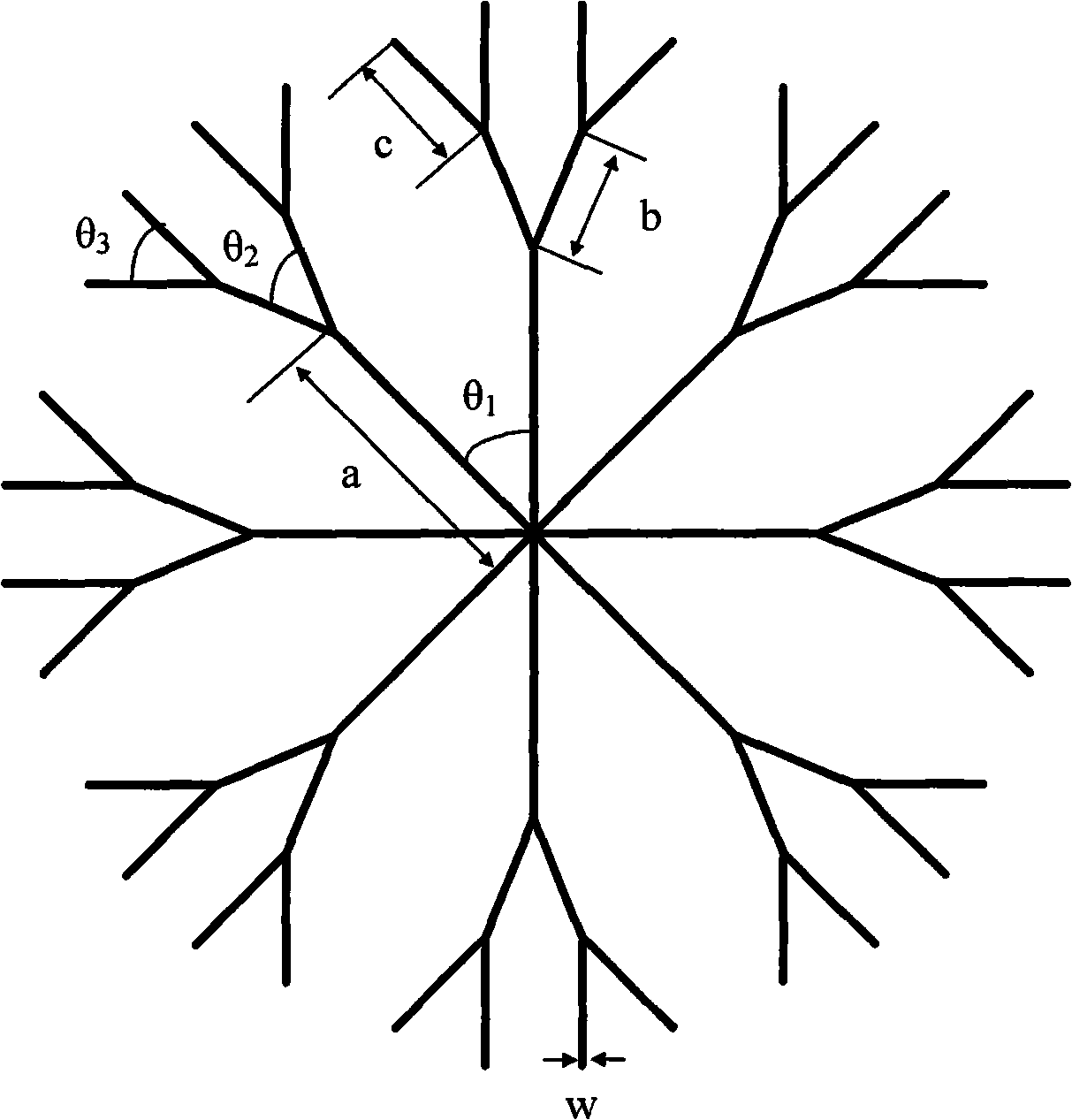
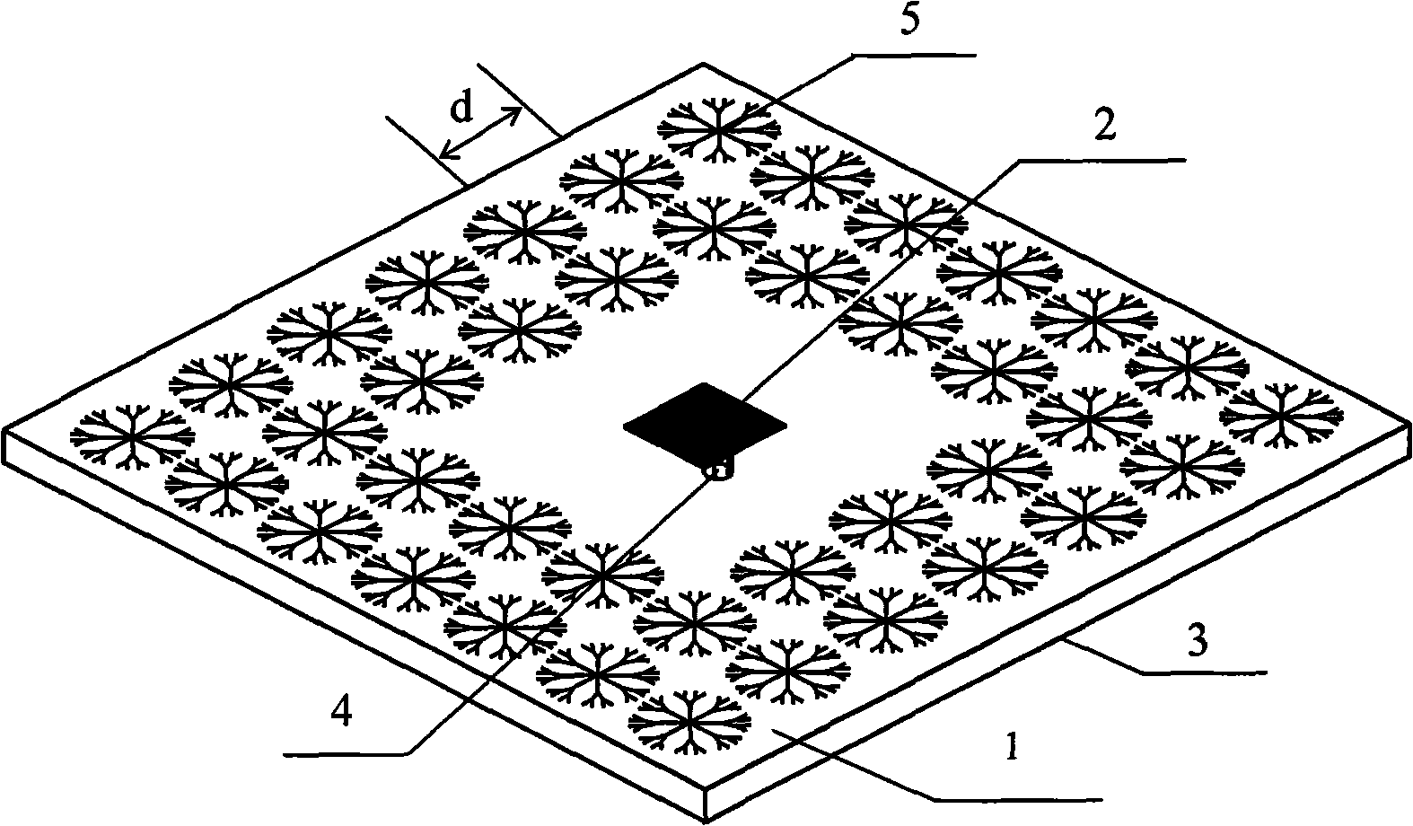
[0017] Using circuit board etching technology, a dendritic structure left-handed material microstrip antenna with a center operating frequency of 10 GHz is produced, such as figure 2 shown. A polytetrafluoroethylene material (ε=2.65) with an area of ​​70mm×70mm and a thickness of 1.5mm is selected as the dielectric substrate 1 of the antenna, and the size of the metal copper radiation patch 2 on one side of the dielectric substrate 1 is 7.9mm×7.9mm. The other side is completely made of metal copper, as the ground plate 3, using coaxial feed, and the SMA coaxial 4 connector connects the metal radiation plate 2 and the metal ground plate 3, and serves as the signal feed source of the antenna. The metal copper dendritic structure unit array 5 is etched periodically around the radiation patch. For the microstrip antenna with a working frequency of 10 GHz in this embodiment, the geometric dimensions of the dendritic structure are: the length of the primary branch a=2.2mm, the seco...

Embodiment 2

[0019] Similar to Embodiment 1, a left-handed material microstrip antenna with a dendritic structure and a center operating frequency of 11 GHz is manufactured by circuit board etching technology. A polytetrafluoroethylene material (ε=2.65) with an area of ​​65mm×65mm and a thickness of 0.8mm is selected as the dielectric substrate of the antenna. The metal radiation patch on one side of the dielectric substrate is 7.3mm×7.3mm in size, and the other side is completely metal , as the antenna ground plate, using coaxial feed, SMA coaxial connector connects the metal radiator and the metal ground plate, and serves as the signal feed source of the antenna. An array of metal dendritic structure units arranged periodically is etched around the radiation patch. For the microstrip antenna whose operating frequency is 11GHz in this embodiment, the geometric dimensions of the dendritic structure are: the length of the first-level branch a=1.9mm, the length of the second-level branch b=1...

Embodiment 3

[0021] Using circuit board etching technology to fabricate a dendritic structure left-handed material microstrip antenna array, Figure 9 It is a four-patch dendritic structure left-handed material microstrip antenna array with a central operating frequency of 10GHz. On one side of the polytetrafluoroethylene dielectric substrate 1 (ε=2.65) with a thickness of 2mm, the metal radiation patch array element 2 is etched, and the other side is completely metal, which serves as the antenna ground plate 3 . The microstrip transmission line is used for feeding, and 4 is the feeder. The metal dendritic structure unit array 5 is etched around the radiation patch. The left-hand material of the dendritic structure used in this embodiment is the same as that in Embodiment 1, and its geometric dimensions are: the length of the primary branch a=2.2mm, the length of the secondary branch b=1.4mm, the length of the third-level branch c=1mm, the angle between two adjacent first-level branches i...


PUM

PropertyMeasurementUnit
Line widthaaaaaaaaaa
Thicknessaaaaaaaaaa
Thicknessaaaaaaaaaa

Abstract

The invention relates to a left hand material micro-strip antenna, in particular to an X-wave range branch-shaped structure left hand material micro-strip antenna. Being different from the existing micro-strip antenna, the branch-shaped structure left hand material is loaded on the micro-strip antenna; a circuit board etching technique is adopted so as to etch the branch-shaped structure left hand material onto the micro-strip antenna substrate. The peculiar electromagnetic behavior of the branch-shaped structure left hand material is used for improving the performance of the antenna, reinforcing the forward radiation of the antenna, concentrating the directionality more and improving the gain of the antenna. The preparation method used for the branch-shaped structure left hand material of the micro-strip antenna of the invention is identical to that of the antenna, adopts the circuit board etching technique, is integrally formed with the micro-strip antenna, and has simple preparation and low cost.

Description

technical field [0001] The invention relates to a left-handed material microstrip antenna, in particular to an X-band dendritic structure left-handed material microstrip antenna. Background technique [0002] The microstrip antenna is composed of a dielectric substrate with a thickness much smaller than the wavelength and metal patches etched on both sides of it. It is fed by a coaxial line or a microstrip line, and passes through the gap between the patch and the ground plate. radiation. Microstrip antenna has the advantages of thin surface, small size, light weight, planar structure, and easy to conform to the surface of missiles, satellites and other carriers. It has been widely used in satellite communications, radar, and remote sensing. However, the structural characteristics of the microstrip antenna itself lead to the disadvantages of low antenna unit gain, poor directivity, and low radiation efficiency due to conductor and dielectric loss. Some existing technologie...

Claims


Application Information

Patent Timeline
IPC IPC(8): H01Q13/00H01Q13/08H01Q1/38
Inventor 赵晓鹏刘亚红
Owner NORTHWESTERN POLYTECHNICAL UNIV
Why Eureka
Try Eureka