2-3GHz band microstrip antenna with negative permeability material

A technology of negative magnetic permeability materials and microstrip antennas, which is applied to antennas, antenna arrays, and structural forms of radiating elements, can solve problems such as poor directivity, low gain, and low radiation efficiency of ordinary microstrip antennas, and achieve a simple process Effect

Inactive Publication Date: 2010-01-13
NORTHWESTERN POLYTECHNICAL UNIV
View PDF0 Cites 8 Cited by
  • Summary
  • Abstract
  • Description
  • Claims
  • Application Information

AI Technical Summary

Problems solved by technology

[0004] The purpose of the present invention is to provide a microstrip antenna with a negative magnetic permeability material as a substrate for the disadvantages of low radiation efficiency, low gain, and poor directivity of ordinary microstrip antennas.

Method used


Image

  • 2-3GHz band microstrip antenna with negative permeability material
  • 2-3GHz band microstrip antenna with negative permeability material
  • 2-3GHz band microstrip antenna with negative permeability material

Examples


Embodiment 1

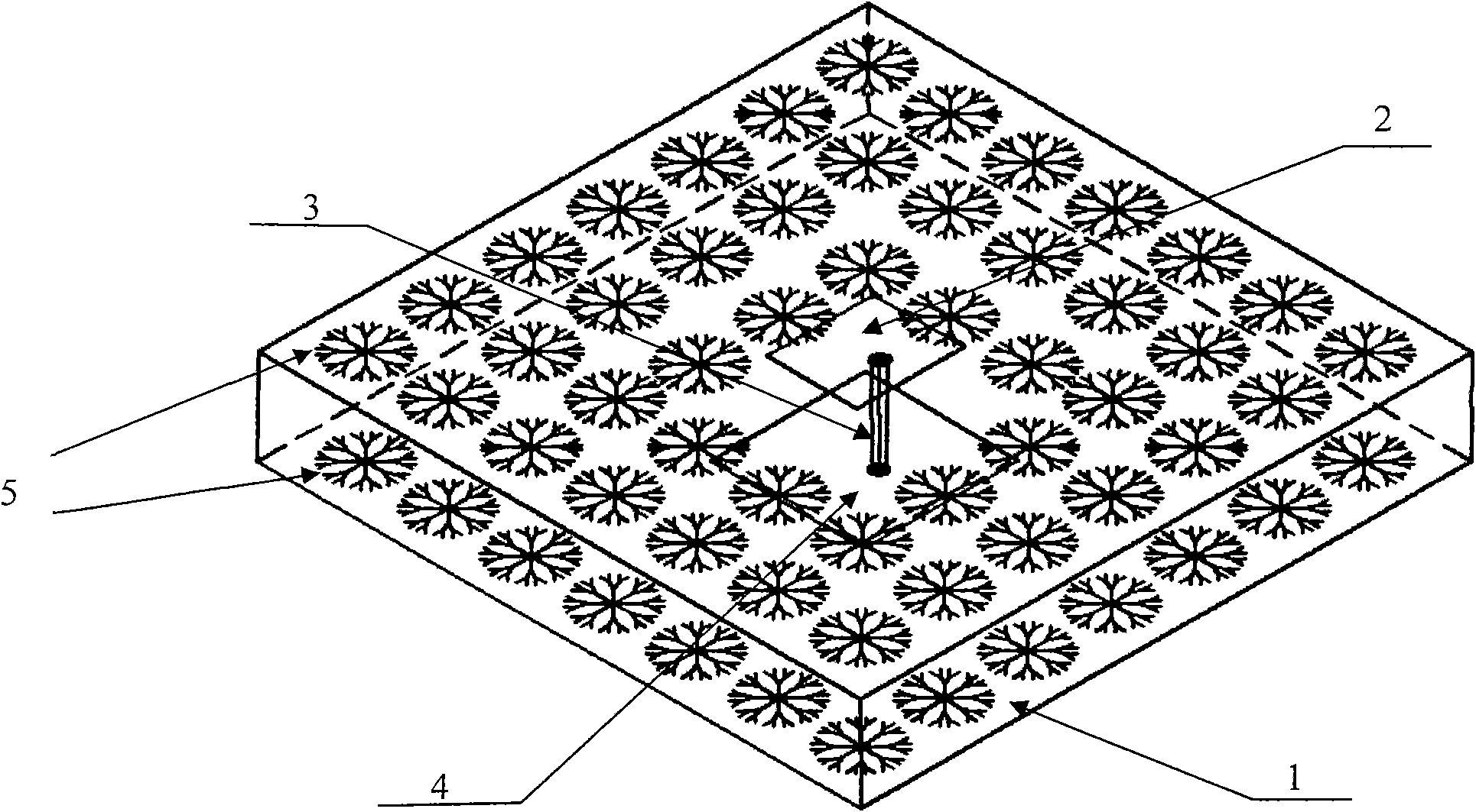
[0018] Using circuit board etching technology, a dendritic negative magnetic permeability material microstrip antenna with a central operating frequency of 2.64 GHz was fabricated. Negative magnetic permeability material microstrip antenna antenna such as figure 1 As shown, a polytetrafluoroethylene material (ε=2.65) with an area of ​​200mm×200mm and a thickness of 1.5mm is selected as the dielectric substrate 1 of the antenna, and the size of the metal copper radiation patch 2 on one side of the dielectric substrate 1 is 42mm×33.8 mm, the size of the square metal copper sheet 4 on the other side is 60mm×60mm, as the ground plate 4, using coaxial feed, the SMA coaxial connector 3 connects the metal radiation sheet 2 and the metal ground plate 4, and serves as the signal feed of the antenna into the source. Fig. 4 is a microstrip antenna of negative magnetic permeability material, and metal copper dendritic structure unit array 5 is etched periodically around the radiation pat...

Embodiment 2

[0020] Similar to Embodiment 1, a microstrip antenna with a dendritic structure and negative magnetic permeability material with a central operating frequency of 2.85 GHz is manufactured by circuit board etching technology. The polyethylene material (ε=2.3) with an area of ​​180mm×180mm and a thickness of 1mm is selected as the dielectric substrate of the antenna. The metal copper radiation patch on one side of the dielectric substrate is 38.4mm×29.8mm in size, and the square metal radiation patch on the other side is The size of the copper sheet is 50mm×50mm. It is used as the ground plane of the antenna, and the coaxial feed is adopted. The SMA coaxial connector connects the metal radiator and the metal ground plane, and serves as the signal feed source of the antenna. The copper surface is tin-plated to prevent oxidation. Copper tinned dendritic structure element arrays are etched periodically around the radiation patch and the metal ground plate. For the negative magnetic ...

Embodiment 3

[0022] Similar to Embodiments 1 and 2, a dendritic structured negative magnetic permeability material microstrip antenna with a central operating frequency of 2.45 GHz was manufactured by circuit board etching technology. Select metal copper with an area of ​​220mm×220mm on one side and epoxy glass cloth material (ε=4.6) with a thickness of 0.8mm as the dielectric substrate of the antenna. The size of the radiation patch on the dielectric substrate is 44.38mm×35.67mm. The size of the square metal copper sheet is 65mm×65mm. It is used as the ground plate of the antenna, and the coaxial feed is used. The SMA coaxial connector connects the metal radiator and the metal ground plate, and serves as the signal feed source of the antenna. The copper surface is silver-plated to prevent oxidation. The metallic copper silver-plated dendrite structure unit array is etched periodically around the radiation patch and the metal grounding plate. For the negative magnetic permeability microst...


PUM

PropertyMeasurementUnit
Metal thicknessaaaaaaaaaa
Thicknessaaaaaaaaaa

Abstract

The invention relates to a 2-3GHz band microstrip antenna with a negative permeability material, in particular to a microstrip antenna with a negative permeability material with two-sided dendritic structures. The microstrip antenna in the invention comprises a dielectric substrate, a metal radiation patch and a metal ground plate; wherein, the metal radiation patch and the metal ground plate are etched at both sides of the dielectric substrate; an SMA connector connects the metal radiation patch and the metal ground plate and serves as a feed-in interface of radio wave signals of the antenna; dendritic structure cell arrays arranged periodically are etched at both sides of the space around the metal radiation patch and the metal ground plate. When electromagnetic waves enter vertically, the negative permeability effects generated by the two-sided dendritic structures can be adopted to improve the transmitting efficiency and directionality of the microstrip antenna and increase the antenna gain.

Description

technical field [0001] The invention relates to a negative magnetic permeability microstrip antenna in the 2-3GHz frequency band. This microstrip antenna improves the performance of the antenna by engraving a dendritic structure negative magnetic permeability material on both sides of the substrate, especially improves the performance of the antenna. The radiation efficiency, gain and directivity of the antenna are determined. Background technique [0002] The ordinary microstrip antenna is composed of three parts: a dielectric plate with a certain thickness, a metal ground plate and a radiation patch. Generally, coaxial line or microstrip line feed is used to excite the electromagnetic field in the gap between the radiation patch and the metal ground plate, and the electromagnetic wave energy is radiated outward through the gap between the patch and the conductor ground plate. Compared with other antennas, microstrip antennas have many advantages: small size, light weight,...

Claims


Application Information

Patent Timeline
IPC IPC(8): H01Q1/38H01Q13/08H01Q21/00
Inventor 赵晓鹏朱忠奎史亚龙纪宁罗春荣
Owner NORTHWESTERN POLYTECHNICAL UNIV
Why Eureka
Try Eureka