Magnetic confinement magnetron sputtering method and magnetron sputtering apparatus manufactured by the method

A magnetron sputtering device and magnetron sputtering technology, applied in sputtering coating, ion implantation coating, metal material coating process, etc., can solve the problems of low target utilization rate and low deposition rate, and achieve Effect of increased deposition rate, increased deposition rate, and increased collision probability

Inactive Publication Date: 2009-01-21
XIAN TECHNOLOGICAL UNIV
View PDF0 Cites 15 Cited by
  • Summary
  • Abstract
  • Description
  • Claims
  • Application Information

AI Technical Summary

Problems solved by technology

[0009] The invention provides a magnetically confined magnetron sputtering method and a magnetron sputtering device prepared by the method to overcome the problems of low target utilization and low deposition rate in the prior art

Method used


Image

  • Magnetic confinement magnetron sputtering method and magnetron sputtering apparatus manufactured by the method
  • Magnetic confinement magnetron sputtering method and magnetron sputtering apparatus manufactured by the method
  • Magnetic confinement magnetron sputtering method and magnetron sputtering apparatus manufactured by the method

Examples


Embodiment 1

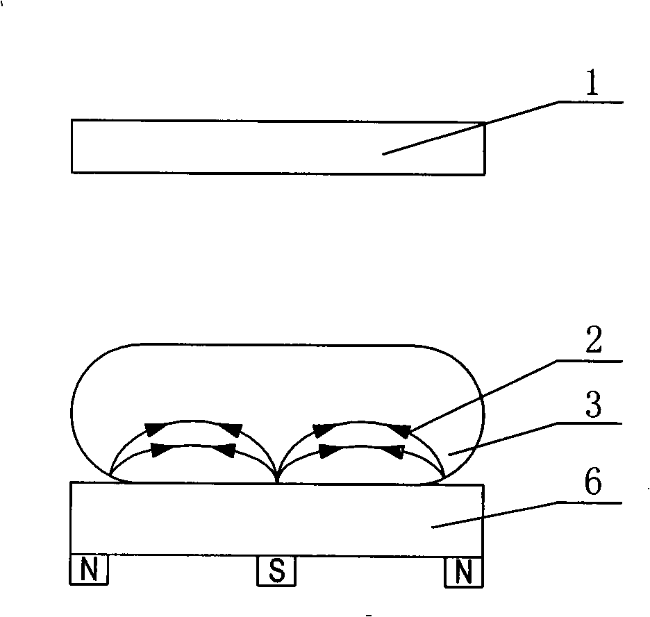
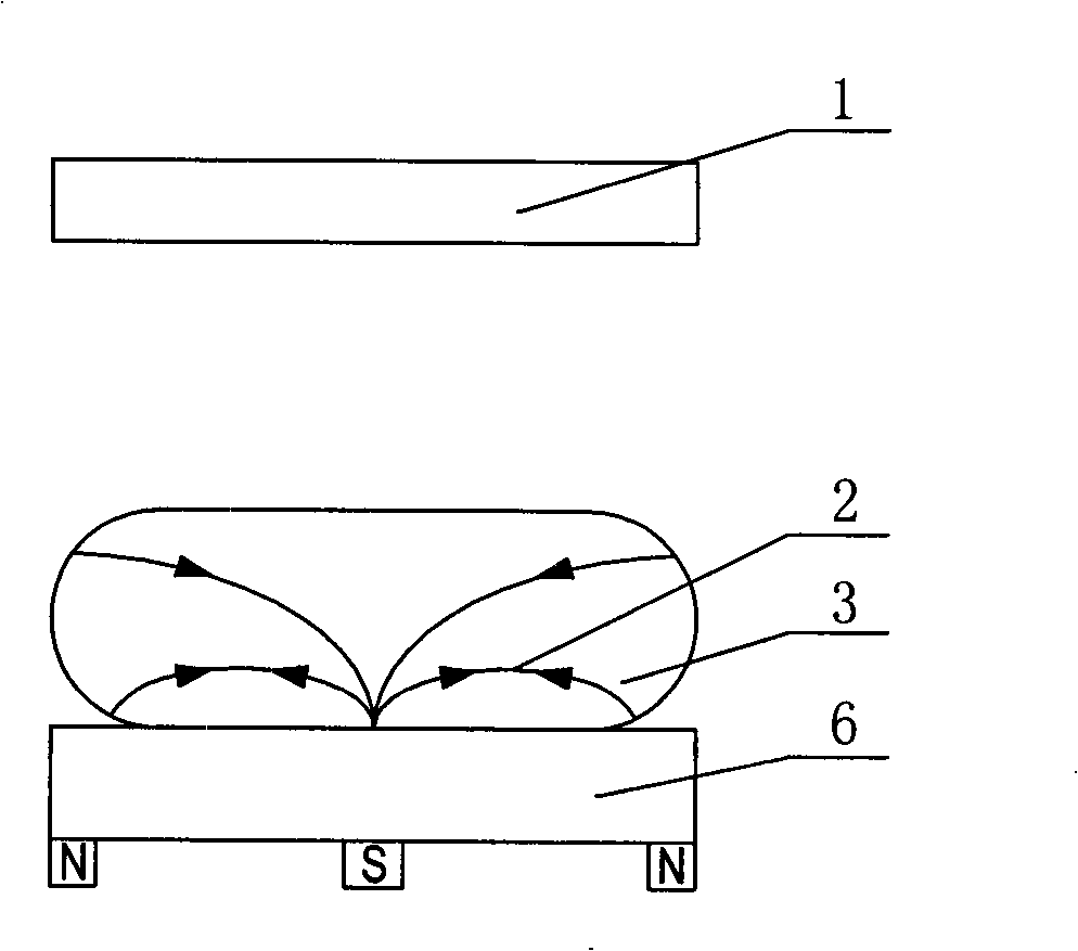
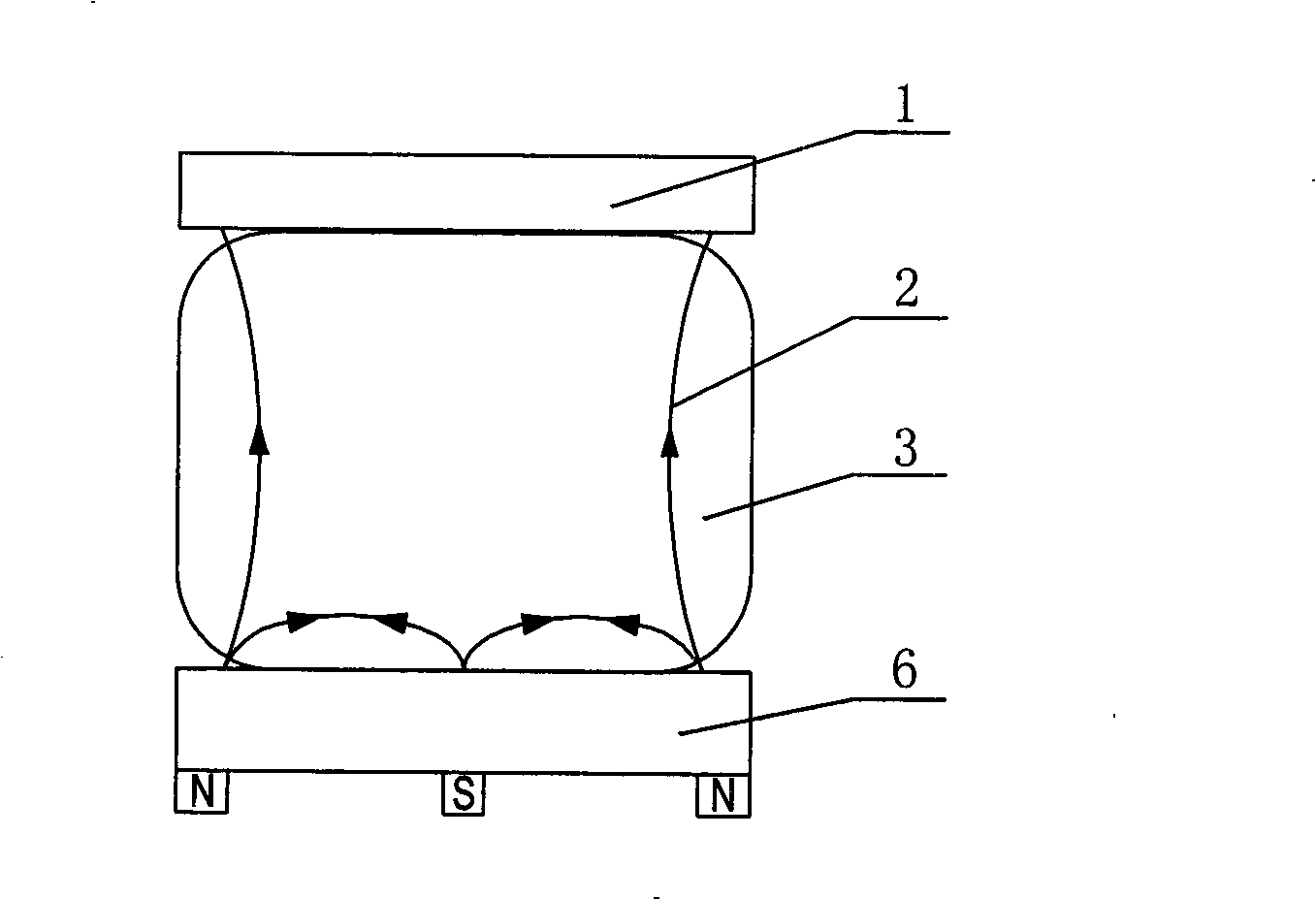
[0027] Example 1, see Figure 4 . A magnetron sputtering device prepared by the above method includes a magnet, a magnetizer 5, a substrate 1 and a sputtering target 7. The magnet is an electromagnet 4, and its opposite magnetic poles are relatively fixedly arranged on the side of the sputtering target. The magnetic conductor 5 constitutes a closed magnetic circuit below.

[0028] The electromagnet 4 is energized, and a magnetic confinement magnetic field 2 is generated in the space formed by the sputtering target 7 and the substrate 1, so that the electrons are confined to the surface area of ​​the target to perform a helical reciprocating motion, which increases the collision probability with the working gas. A plasma region 3 is formed on the surface of the target 7 , and under the action of an electric field, positive ions are accelerated to collide with the target and sputtered out, and the atoms are deposited on the surface of the sputtering target 6 to form a thin film...

Embodiment 2

[0030] Example 2, see Figure 5 . A magnetron sputtering device prepared by the above method, comprising a magnet, a magnetizer 5, a substrate 1 and a sputtering target 7, said magnet is a permanent magnet 8, and the permanent magnet 8 includes three pairs prepared into strips, The three pairs of permanent magnets 8 are fixedly arranged on the side of the sputtering target 7 sequentially from inside to outside.

[0031] Three pairs of permanent magnets 5 generate a magnetic confinement magnetic field 2 in the space formed between the substrate 1 and the sputtering target 7. The working principle is the same as in embodiment 1, except that multiple pairs of permanent magnets are used, which can effectively increase the magnetic field strength. , the electrons are confined to spiral reciprocating motion in a larger area above the surface of the target, which increases the probability of collision with the working gas and improves the bombardment of the ion team on the surface o...


PUM


Abstract

The invention relates to a magnetic confinement magnetron sputtering method and a magnetron sputtering device prepared by use of the same. As the prior art adopts a balanced magnetron sputtering mode and an unbalanced magnetron sputtering mode, the target material utilization rate can only be raised to be between 20 and 35 percent even if permanent magnet movement or the transformation of a plurality of electromagnetic coil sets is adopted, and the prior art has the problems of complex structure and high processing cost. The magnetic confinement magnetron sputtering method forms a magnetic confinement magnetic field with the overall direction parallel to a target surface above the surface of a sputtering target. The magnetron sputtering device manufactured by use of the method comprises a magnet, a magnetic conductor, a substrate and the sputtering target, wherein contrary magnetic poles of the magnet are oppositely fixed on the sides of the sputtering target; the magnetic confinement magnetic field generated by the magnet is positioned between the substrate and the sputtering target, and a connecting line of the two magnetic poles is parallel to the target surface. The magnetron sputtering device can effectively overcome the problem that the prior art is low in target material utilization rate and deposition rate.

Description

1. Technical field [0001] The invention belongs to magnetron sputtering coating technology, in particular to a magnetically confined magnetron sputtering method and a magnetron sputtering device prepared by the method. 2. Technical background [0002] At present, magnetron sputtering technology is widely used in the preparation of surface modification, decorative film, optical film, superconducting film and functional film. Compared with traditional thermal evaporation coating, plasma coating technology has many advantages. The energy of sputtering, unbalanced magnetron sputtering and pulsed arc deposition ions (atoms) is 10 to 100 times higher than that of thermal evaporation, which increases the aggregation density of the film and makes the characteristics of the film layer tend to be more bulky, thus increasing the The strength of the film layer, the mixing of surface materials between the film layers also improves the adhesion, and sometimes even reduces the high tensile...

Claims


Application Information

Patent Timeline
Patent Type & Authority Applications(China)
IPC IPC(8): C23C14/35C23C14/54
Inventor 弥谦杭凌侠郭忠达梁海峰徐均琪孙国斌惠迎雪
Owner XIAN TECHNOLOGICAL UNIV
Why Eureka
Try Eureka