Optical coating method and optical film coater using the method

An optical coating machine and optical coating technology, applied in optics, optical components, sputtering coating, etc., can solve the high investment cost of equipment, the inability to meet the requirements of optical thin film and optoelectronic functional multilayer thin film and optoelectronic microsystem preparation, etc. problems, to achieve the effect of reducing equipment investment, reducing equipment investment costs, and improving quality and pass rate

Inactive Publication Date: 2009-02-04
XIAN TECH UNIV
View PDF0 Cites 5 Cited by
  • Summary
  • Abstract
  • Description
  • Claims
  • Application Information

AI Technical Summary

Problems solved by technology

[0004] The present invention provides an optical coating method and an optical coating machine using the method, so as to solve the problems existing in the prior art that cannot meet various optical thin films, optoelectronic functional multilayer thin films, and optoelectronic microsystems, and the cost of equipment investment is high The problem

Method used


Image

  • Optical coating method and optical film coater using the method
  • Optical coating method and optical film coater using the method
  • Optical coating method and optical film coater using the method

Examples


Embodiment Construction

[0019] The present invention will be described in detail below in conjunction with the accompanying drawings.

[0020] An optical coating method, which combines cathode vacuum arc coating technology, magnetron sputtering coating technology and thermal evaporation coating technology according to the type of film. convert.

[0021] When used in combination, the parameters still use the well-known parameters when used alone.

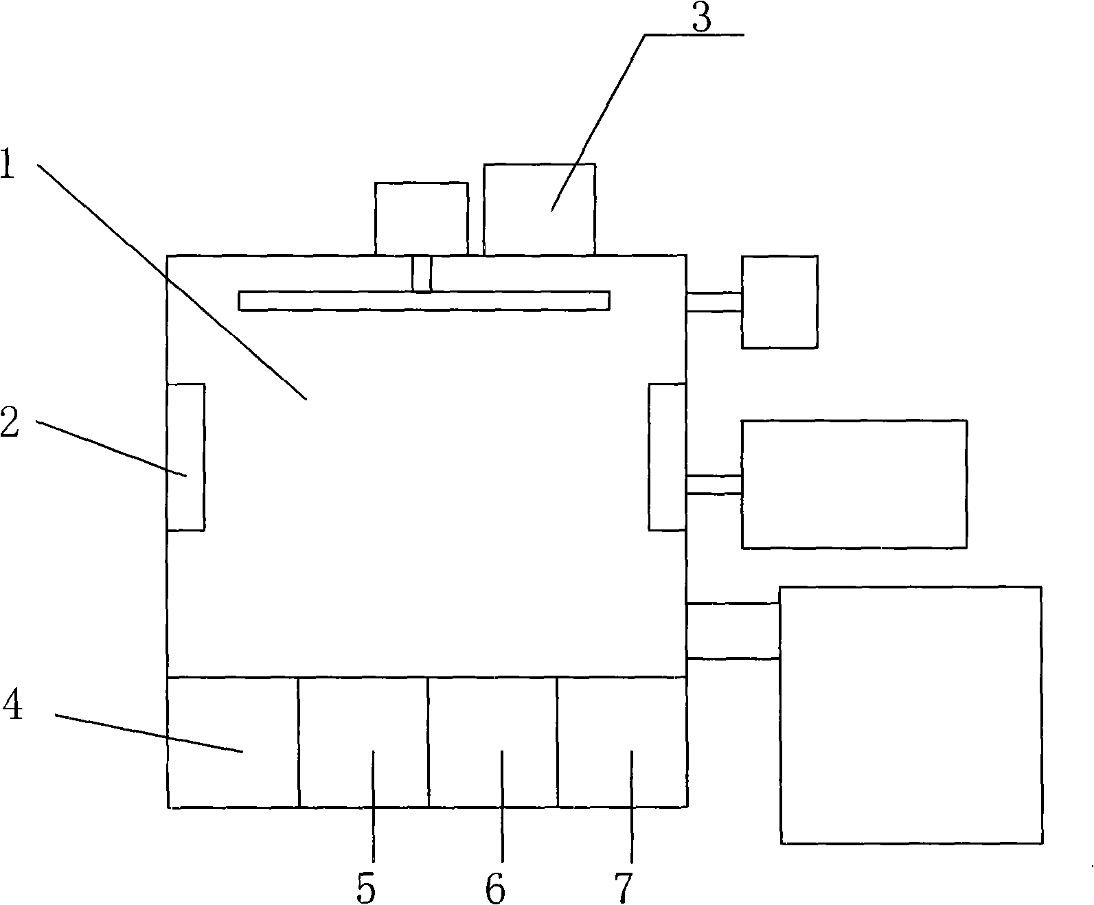
[0022] see figure 1 . An optical coating machine comprises a vacuum coating chamber 1, a temperature control system 2, a film thickness control system 3, a gas flow supply and control system and a thin film evaporation system. Said thin film evaporation system includes cathode vacuum arc emission device 4 , magnetron sputtering device 5 , thermal evaporation device 6 and auxiliary deposition ion source device 7 .

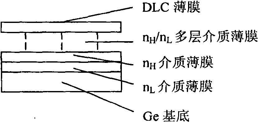
[0023] Use Example 1: Preparation of 3 micron to 5 micron infrared anti-reflection optical film.

[0024] see figure 2 , where n H =2.4,...


PUM

PropertyMeasurementUnit
diameteraaaaaaaaaa

Abstract

The invention relates to the technical field of optical manufacturing and photoelectric component production equipment, in particular to an optical coating method and an optical coating machine which uses the optical coating method. The invention aims to solve the problems that the prior art can not meet the demands of the preparation of various optical films, optoelectronic functional multi-layer films, as well as photoelectric micro-systems, and the equipment investment is high. To solve the problems in the prior art, the following technical proposal is provided: an optical coating method combines the vacuum cathodic arc coating technology, the magnetron sputtering coating technology and the thermal evaporation coating technology in accordance with the types of the films; during the using process, the plated piece is maintained in a vacuum state and carries out rapid conversion of the evaporation source in a real-time way. At the same time, the invention provides an optical coating machine which comprises a vacuum coating chamber, a temperature control system, a film thickness control system, a gas flow providing and control system, as well as a thin-film evaporation system; and the thin-film evaporation system comprises a cathodic vacuum arc generator, a magnetron sputtering device and a thermal evaporation device.

Description

technical field [0001] The invention relates to the technical field of optical manufacturing and photoelectric component production equipment, in particular to an optical coating method and an optical coating machine using the method. Background technique [0002] At present, optoelectronic technology has been applied to various fields in people's lives, such as photography, light display, infrared night vision, various optoelectronic components, aerospace, aviation and other fields. The demand for optical films is reflected in high damage threshold laser films, multi-band optical films and protective films, especially in high-precision film systems and photoelectric functional films that require high optical indicators. The wavelength reflects a wide band, from ultraviolet, visible, near-infrared to mid-infrared (200nm-12000nm), the main types are anti-reflection film, high-reflection film, spectroscopic film, polarizer, various narrow-band and cut-off filters, etc. . For...

Claims


Application Information

Patent Timeline
Patent Type & Authority Applications(China)
IPC IPC(8): G02B1/10C23C14/26C23C14/30C23C14/35
Inventor 杭凌侠弥谦刘卫国徐均琪梁海峰潘永强惠迎雪
Owner XIAN TECH UNIV
Why Eureka
Try Eureka