MEMS electromagnetic band gap adjustable band-elimination filter applied to K wave band

An electromagnetic bandgap, K-band technology, applied in the field of adjustable center frequency bandstop filter, can solve the problems of narrow filter tuning range, small capacitance change, limited application of adjustable bandstop filter, etc. Difficulty, good isolation performance, easy monolithic integration effect

Inactive Publication Date: 2009-02-04
INST OF OPTICS & ELECTRONICS - CHINESE ACAD OF SCI
View PDF0 Cites 17 Cited by
  • Summary
  • Abstract
  • Description
  • Claims
  • Application Information

AI Technical Summary

Problems solved by technology

However, in the existing MEMS electromagnetic bandgap tunable bandstop filter, due to the pull-in phenomenon of the MEMS switch capacitor, the capacitance cha

Method used


Image

  • MEMS electromagnetic band gap adjustable band-elimination filter applied to K wave band
  • MEMS electromagnetic band gap adjustable band-elimination filter applied to K wave band
  • MEMS electromagnetic band gap adjustable band-elimination filter applied to K wave band

Examples


Embodiment Construction

[0023] The present invention will be described in detail below in conjunction with the accompanying drawings and specific embodiments.

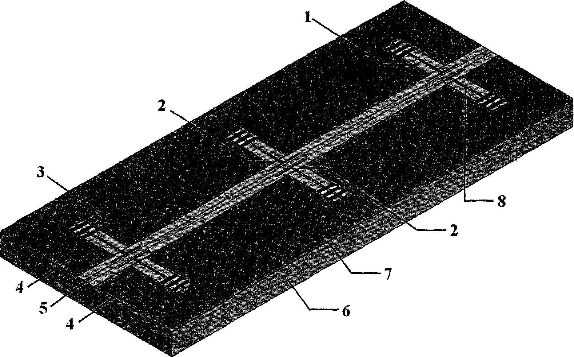
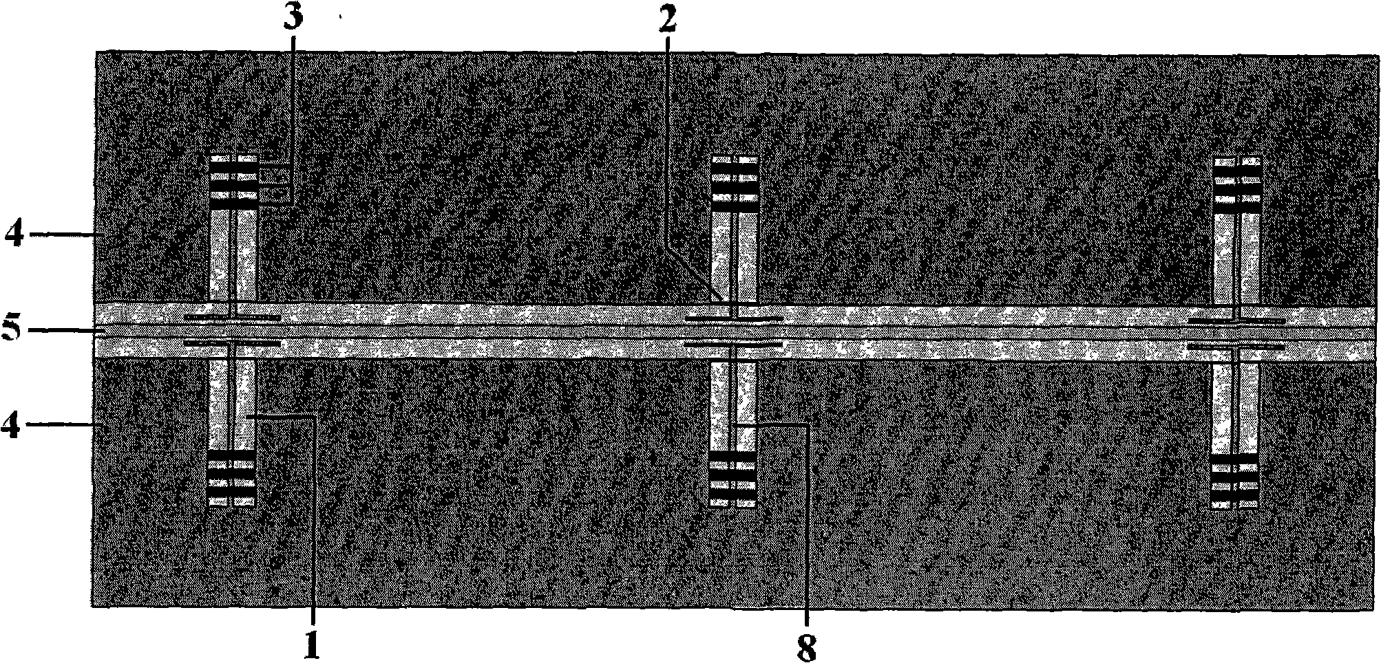
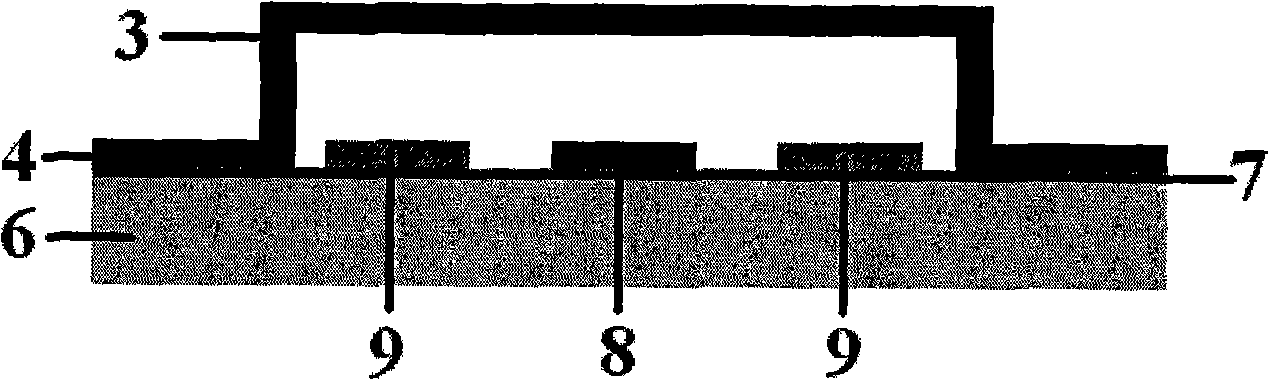
[0024] Such as figure 1 and figure 2 As shown, it is respectively a perspective view and a top view of a MEMS electromagnetic bandgap (EBG) tunable bandstop filter applied to the K-band in an embodiment of the present invention; the substrate 6 of the present embodiment selects a relative permittivity of 11.9, a thickness of 675 μm silicon material; the coplanar waveguide central transmission line 5 and the coplanar waveguide ground plane 4 are composed of a metal gold layer with a thickness of 2 μm, and are located on the silicon substrate 6. The thickness of the 2 μm gold layer is greater than the skin depth of the K-band microwave signal, It is beneficial to reduce the conductor loss of the transmission line; wherein the central transmission line 5 of the planar waveguide is located on the longitudinal center line of the ground plane 4 o...


PUM


Abstract

Disclosed is an MEMS electromagnetic band gap tunable band-stop filter used in K wave band, wherein a coplanar waveguide center transmission line is arranged on a vertical center line of a coplanar waveguide ground plane, both of which are disposed on a substrate, and carved grooves are arranged in the direction which is vertical to the coplanar waveguide center transmission line; the horizontal ends of a pair of T-shaped lines are respectively parallel to the coplanar waveguide center transmission line and are symmetrically distributed on both sides thereof, and the vertical ends are respectively arranged in the carved grooves on both sides of the coplanar waveguide center transmission line; two ends of a pair of air-bridge span over the opening of the edge of the carved groove which is near the coplanar waveguide center transmission line; two ends of a pair of MEMS direct-contact switching group span across two tail ends of the carved groove which is along the direction of keeping away from the coplanar waveguide center transmission line; the unit resonant circuits formed by the foregoing structure are collocated cyclically along the direction of the coplanar waveguide center transmission line to form the MEMS electromagnetic band gap tunable band-stop filter used in K wave band; and the invention adopts an MEMS switch to achieve wide-range tuning of the filter center frequency, and introduce the electromagnetic band gap structure to achieve good isolation performance within the stop band.

Description

technical field [0001] The invention relates to the technical field of radio frequency micro-electromechanical systems (RF MEMS), in particular to a center frequency adjustable band-stop filter based on MEMS and an electromagnetic bandgap structure suitable for K-band. Background technique [0002] Tunable filters are widely used in modern microwave / millimeter wave applications such as multi-band wireless communications, wideband radar systems, and wideband tracking receivers. Traditional tunable filters usually use YIG resonators, active resonators, or varactors as tunable components, but they often obtain low Q values, and also have disadvantages such as high manufacturing costs, large volume, and high power consumption. With the development of MEMS technology, MEMS switches have gradually been widely researched and used in the field of tunable filters due to their advantages of low loss, high linearity, extremely low power consumption, and small size. Electromagnetic ban...

Claims


Application Information

Patent Timeline
IPC IPC(8): H01P1/212
CPCH01P1/2005
Inventor 姚军张理邱传凯
Owner INST OF OPTICS & ELECTRONICS - CHINESE ACAD OF SCI
Why Eureka
Try Eureka