Plate-type heat-pipe radiator and use thereof

A plate heat pipe and radiator technology, applied in indirect heat exchangers, instruments, electric solid devices, etc., can solve the problems of large air eddy current loss, reduced working medium circulation area, and high price, so as to reduce air flow resistance and heat transfer Improve and increase the effect of air flow

Inactive Publication Date: 2009-02-18
秦彪
View PDF0 Cites 13 Cited by
  • Summary
  • Abstract
  • Description
  • Claims
  • Application Information

AI Technical Summary

Problems solved by technology

The problems of such a radiator are: the air outlet is concentrated, if it is blocked, the heat will not come out; the air driven by the fan passes through the ribs and is directly discharged without further use; the fan cover occupies most of the space of the fan, and is Empty, in order to reduce the space occupied by the windshield, the windshield is not a standard volute shape, so the air vortex loss is very large, and the air flow distribution at the air outlet is uneven, which is not good for heat dissipation
[0004] The heat pipes in the existing radiators are all tubular structures, and the bending radius of the tubular structures is limited, which is not conducive to the compactness of the radiator
In order to reduce the thickness, flat tubes are used, but if the tube heat pipe is too flat, the flow area of ​​the working medium in the heat pipe will be reduced, and the heat transfer capacity of the heat pipe will be reduced, so the thickness of the tube heat pipe is limited, which affects the radiator. The thickness is reduced
[0005] Due to the heat dissipation problem of the CPU or GPU chip, the radiators in the current notebook computers cannot be standardized in series, and the internal structure layout of the computer is ever-changing. Different series have completely different design layouts. Even if the same series, due to the function and performance improvement , a major change had to be made simply because of thermal issues
This makes the product design cost high and the mold cost high, causing the performance of the notebook computer to be far inferior to that of the desktop computer, but the price is higher than that of the desktop computer.

Method used


Image

  • Plate-type heat-pipe radiator and use thereof
  • Plate-type heat-pipe radiator and use thereof
  • Plate-type heat-pipe radiator and use thereof

Examples


Embodiment Construction

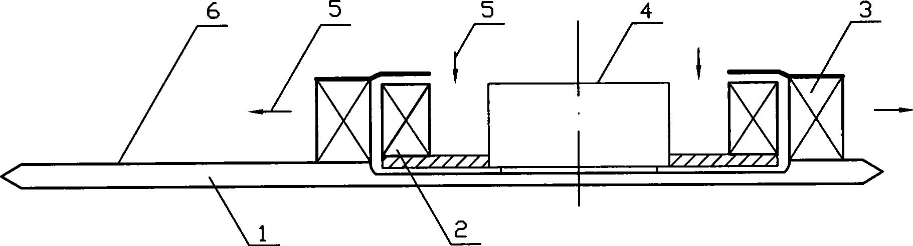
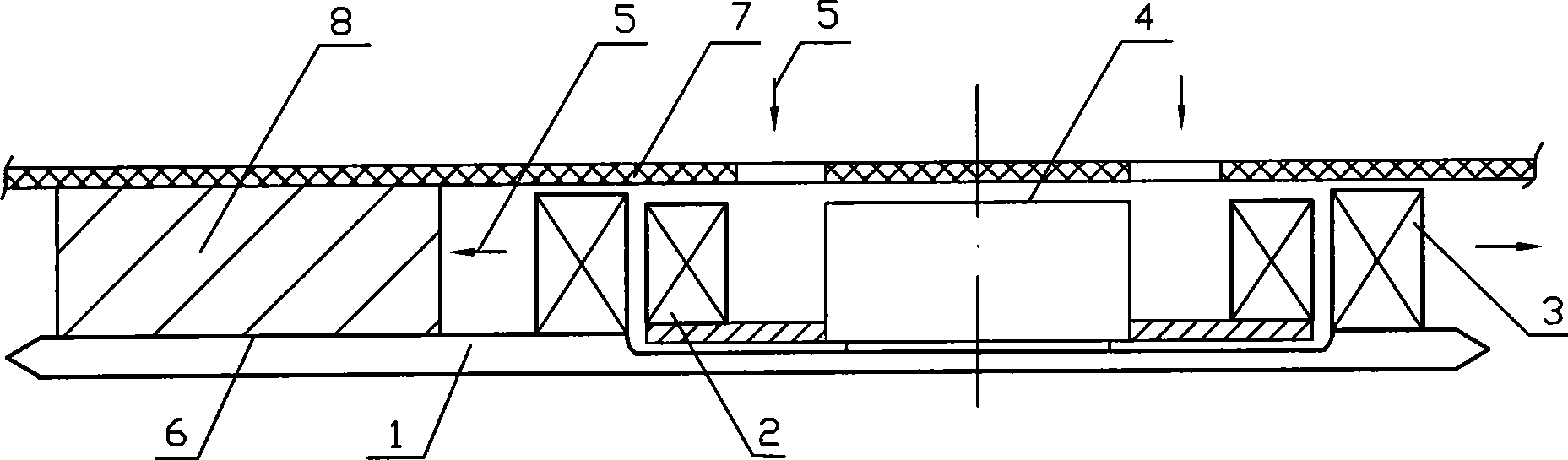
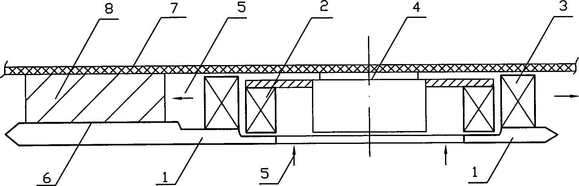
[0030] figure 1 The typical features of the radiator of the present invention are shown. The fan 4 is a centrifugal type with axial air intake and radial outflow. The outer circumference of the impeller 2 of the fan 4 is an air outlet, and the air convection expansion heat exchange surface 3 faces the impeller 2 air outlet, the air driven by the impeller 2 directly enters the air convection expansion heat exchange surface 3. The heat pipe 1 has a plate structure, and the air convection heat exchange surface 3 is directly arranged on the heat pipe 1, and the heat absorption surface 6 is next to it. Where the fan is located, the heat pipe is designed with a concave shape, so that the height of the blades of the impeller 2 and the height of the motor can be increased without increasing the thickness of the radiator, and the air flow of the fan can be increased. In order to prevent the hot air discharged from the radiator from flowing back to the fan intake and reduce the heat dissi...


PUM


Abstract

The invention provides a plate-type heat pipe radiator and applications thereof in a portable computer. In the radiator of the invention, the heat pipe (1) adopts a plate-type structure such that an air convection extended heat-exchange surface (3) (namely a rib) provided thereon surrounds and faces an impeller (3) of a fan (4), thus saving a fan housing and occupied space and cost thereof, shortening distance for heat transfer in the heat pipe (1) and compacting the radiator to a large extent. The heat dissipating capacity is further improved by incorporating strengthened convection heat transfer structure and setting the rib in accordance with aerodynamics. The radiator has lessened mounting limit on a main board (7), which can realize series standardization of the radiator. Three portable computers are set forth using the inventive radiator, thus making the computer performance higher, lighter, lower in cost and more convenient for users on the basis of enhancement of heat dissipating capacity.

Description

Technical field [0001] The present invention relates to a heat dissipation device for electronic devices, especially a flat shape, adopts a heat pipe and a centrifugal fan, and is mainly used for heat dissipation of electronic chips (such as CPU or GPU) in portable electronic products, such as portable (notebook) computers. Background technique [0002] The thickness requirements of portable computers are getting thinner and thinner, their performance is constantly improving, and the heat generation is increasing, especially the heat generation of the central processing unit chip CPU and the graphics processor chip GPU has increased significantly, and heat dissipation has become the bottleneck of the development of portable computers. The radiator is like a volute that cannot be thrown away on the back of a snail. It is pasted on the CPU or GPU chip. The volume of the radiator has taken up a considerable space in the portable computer. The thickness of the portable computer is re...

Claims


Application Information

Patent Timeline
Patent Type & Authority Applications(China)
IPC IPC(8): H01L23/34H01L23/427H01L23/467G06F1/16G06F1/20H05K7/20
CPCH01L2924/0002F28D15/0233
Inventor 秦彪
Owner 秦彪
Why Eureka
Try Eureka