
Single bus sensor network protocol

A sensor network and single-bus technology, applied in the direction of bus network, data exchange network, transmission system, etc., can solve the problems of high real-time requirements, inability to expand functions, and poor scalability of sensor networks, so as to improve economic applicability and improve Application versatility and the effect of saving development costs

Inactive Publication Date: 2009-02-25
ZHEJIANG GONGSHANG UNIVERSITY
View PDF0 Cites 31 Cited by
  • Summary
  • Abstract
  • Description
  • Claims
  • Application Information

AI Technical Summary

Problems solved by technology

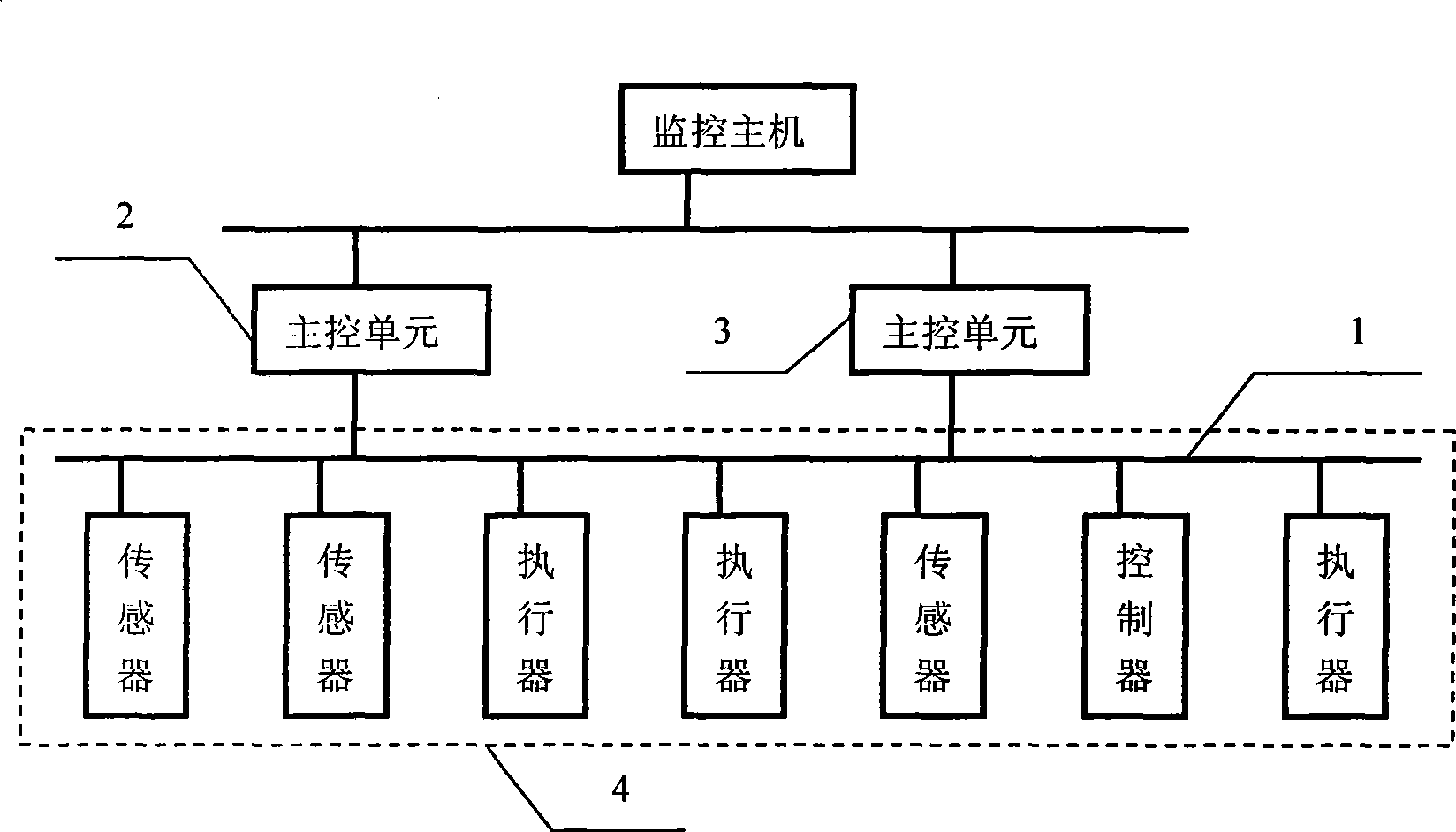
However, the existing protocols are not completely suitable for the front-end components of the process monitoring system (such as sensors, actuators, and controllers, etc.), mainly due to: (1) For cost considerations, nodes have less computing and storage resources, while existing communication protocols The stack (such as TCP / IP, DeviceNet, etc.) is more complex; (2) the link layer protocol of some buses is suitable for network data communication (such as Ethernet), while a single node in the sensor network transmits less data and the transmission content is relatively large. Simple; (3) The sensor network has high real-time requirements, and some asynchronous events must be fed back and processed in real time
[0004] In addition, most of the existing application layer protocols are divided into two categories, one is tailored according to the application of the sensor itself, such as the Dallas temperature sensor DS18B20 (1-wire protocol), the function cannot be expanded, but it is easy to use without modifying the sensor Internal software (solid) hardware design; the other is general, such as nodes based on LonWorks network, the protocol only provides the communication mechanism between nodes, developers also need to carry out secondary development according to node characteristics and application background
Because the former method is only for fixed applications, the scalability is poor, while the latter method requires the developer of the sensor / actuator to master the user's application background, and the adaptability is limited.

Method used


Image

  • Single bus sensor network protocol
  • Single bus sensor network protocol
  • Single bus sensor network protocol

Examples


Embodiment Construction

[0030] The invention is independent of the physical medium, and the interface design can receive changes on the network communication line, but does not define the physical medium.

[0031] The protocol stipulates the process of realizing the plug-and-play feature of slave nodes by identifying frames. When the slave node accesses the bus for the first time or after receiving the master node reset frame, the slave node is set to reset state. The slave node in the reset state sends an identification frame when the bus is idle, and after the master node confirms, the slave node enters the running state. Only slave nodes in running state can receive and send data normally.

[0032] The master node can maintain a slave node table, which records the attributes and configuration information of each node. When the master node finds a new slave node, it will add the node to the table, then query and record the relevant attributes of the newly added node, such as node type, name, chan...


PUM


Abstract

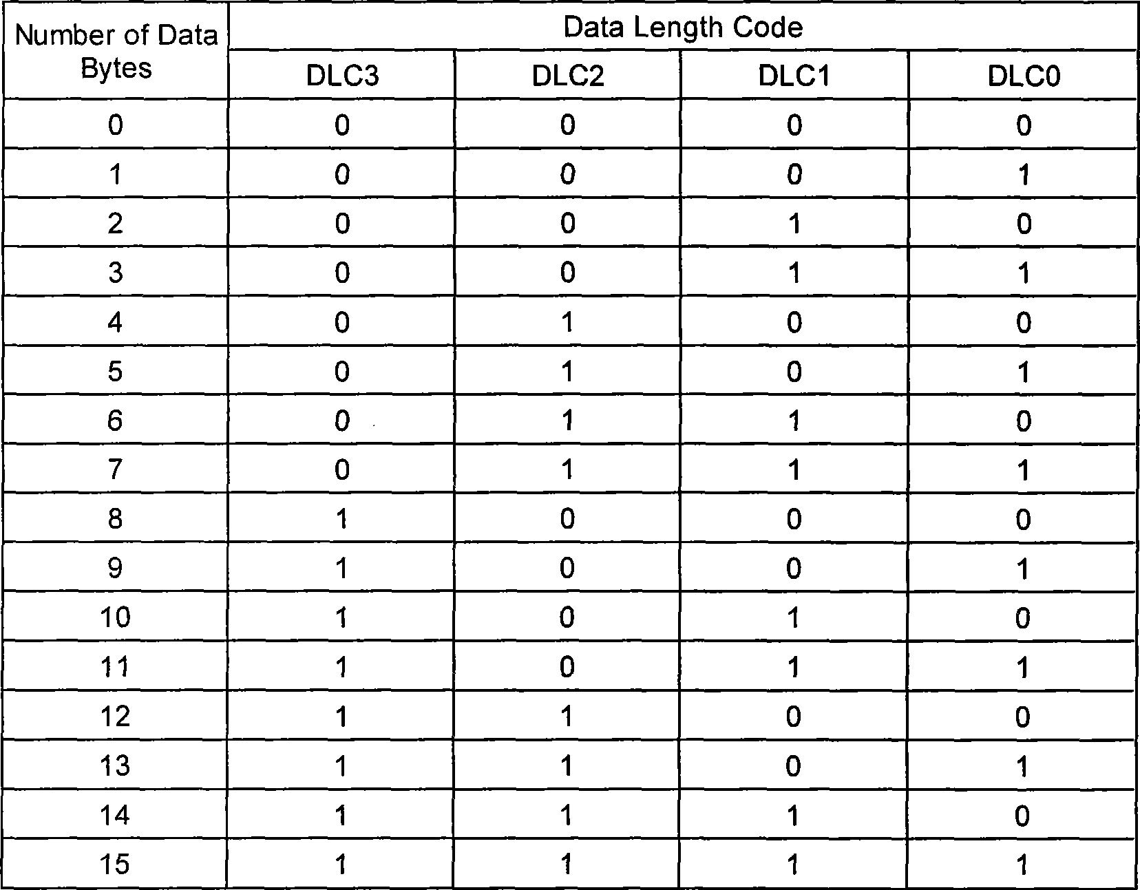
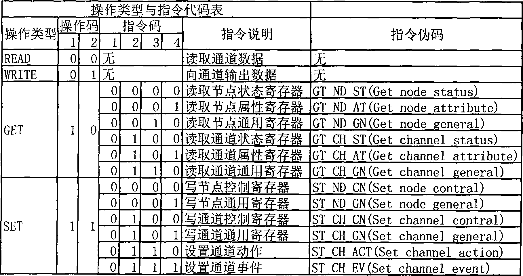
The invention relates to a unibus sensor network protocol which follows the ISO / OSI standard model and provides a physical layer, a data link layer and an application layer. The physical layer defines a substrate communication medium, a driving mode and the form of a connecting terminal. The unibus sensor network protocol is characterized in that the data link layer defines the space size of the address of a node and the addressing method, the maximal transmitting data byte number, the composition method of data frames, the verification method and the arbitration method; during the compunctions process, the data of the application layer is transmitted in a manner of being packed in the data field of the link layer, the data of the application layer include the operating codes, the channel numbers, the command codes, the parameters related to the command codes, the transmitted data, the filling data, and the length, the parameters and the data total length of the parameter data of one frame. The unibus sensor network protocol supports both the master-slave communication mode and the event / action communication mode and improve the flexibility of network organization; supports a bit-based non-destructive bit-by-bit arbitration mode; meets the real-time requirement; supports the node event, the action configuration and the channel operation of the node; reduces the burdens of the host machine; facilitates the integration of the nodes; and reduces the production cost of the product.

Description

technical field [0001] The invention relates to a network control system which generally uses a large number of sensors, actuators and controllers to complete the monitoring and automation of industrial field processes in textile, chemical, food, water treatment and other industries, and specifically relates to a digital communication network protocol. Background technique [0002] There are many types and quantities of on-site monitoring equipment for industrial processes. For example, a grain detection system with a capacity of 50,000 tons includes multiple sensors, transmitters, actuators, controllers, etc., of which more than 4,000 grain temperature sensors are required , and are distributed in a monitoring area with a radius of 2 square kilometers. Based on the characteristics of on-site monitoring of industrial processes, if the traditional analog sensor + host + multi-channel acquisition card or slave computer is used, a large number of cables, terminals, slot boxes,...

Claims


Application Information

Patent Timeline
IPC IPC(8): H04L12/26H04L29/08H04L12/40
Inventor 琚春花邢建国赵文敏袁鑫朱微微黄菁
Owner ZHEJIANG GONGSHANG UNIVERSITY
Learn More