Combined jet impeller underwater aeration machine

A combined jet and aerator technology, applied in water aeration, biological water/sewage treatment, water/sludge/sewage treatment, etc. All-weather operation and other problems, to achieve the effect of eliminating hidden dangers, convenient installation and connection, maintenance and repair, and avoiding waste of electric energy

Inactive Publication Date: 2009-03-04
张鑫珩 +2
View PDF0 Cites 9 Cited by
  • Summary
  • Abstract
  • Description
  • Claims
  • Application Information

AI Technical Summary

Problems solved by technology

The structure of all similar products in the world has the following problems: (1) At present, the motor and reducer of the aerator are hoisted from the top of the pool cover, while the impeller has to be hoisted from the bottom of the pool cover due to its large diameter and heavy weight It is connected and fixed with the reducer. When there is water in the pool, all the aerators in the same group must be stopped at the same time during maintenance; the activated sludge water in the pool must be completely released; after the pool is rinsed, the operator can The impeller is disassembled in the pool, and it can be restarted after the maintenance is completed. During the maintenance process, the sewage treatment must be stopped, but the sewage in the city is continuously discharged, so it must be operated around the clock. The shutdown maintenance can only discharge the sewage directly, so it is not necessary. It can be shut down, which causes a lot of trouble and many unsafe hidden dangers to maintenance and repair, and some even drop the impeller in the depth of the sewage pool during operation and cannot be salvaged; (2) the current impeller has a single shape and structure, and can only Surface aeration is performed, but middle and deep water layers cannot be aerated, resulting in uneven dissolved oxygen in the surface, middle, and deep water of the pool. The dissolved oxygen in the water is high in the surface layer, low in the middle layer, and absent in the deep
Low power efficiency leads to inflated sewage treatment costs, which does not conform to the national industrial policy of "energy saving and consumption reduction"

Method used


Image

  • Combined jet impeller underwater aeration machine
  • Combined jet impeller underwater aeration machine
  • Combined jet impeller underwater aeration machine

Examples


Embodiment Construction

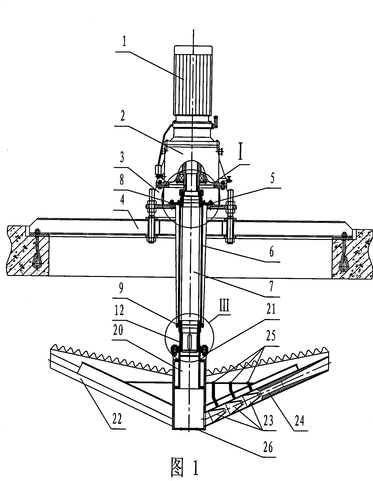
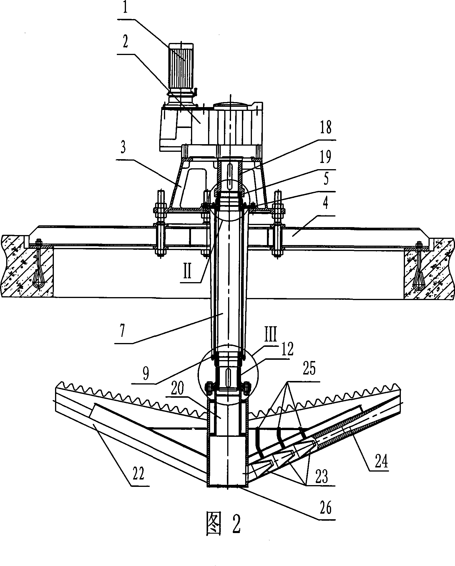
[0028] In Figure 1, Figure 2 and Figure 5Among them, the combined jet impeller underwater aerator of the present invention includes a motor 1, a reducer 2, a mounting beam frame 4, a transmission member and an impeller 20, and the reducer 2 can be an eccentric output shaft reducer or a concentric output shaft reducer, The reducer 2 in Figure 1 is a concentric output shaft reducer, the reducer 2 in Figure 2 is an eccentric output shaft reducer, the motor 1 and the reducer 2 are fixedly connected by bolts, and the blades 22 are fixed on the impeller 20 radially , the bottom of the impeller 20 is provided with a water inlet 26, the bottom of the reducer 2 is provided with a base 3, the upper plane of the base 3 and the reducer 2 are fixedly connected by bolts, and the lower plane is fixedly installed on the installation beam 4, The upper end of the transmission part passes through the base 3 and is slidingly connected with the output shaft of the reducer 2, and the lower end is ...


PUM


Abstract

The invention discloses a combined jet blade wheel underwater aerator which comprises a motor (1), a reductor (2), a mounting frame (4), a transmission mechanism and a blade wheel (20). The motor (1) is fixedly connected with the reductor (2). Blades (20) are radially fixed on the blade wheel (20). A water inlet hole (26) is formed at the bottom of the blade wheel (20). The combined jet blade wheel underwater aerator is characterized in that a pedestal (3) is arranged at the bottom of the reductor (2); the upper surface of the pedestal (3) is fixedly connected with the reductor (2) and the lower surface thereof is fixedly mounted on the mounting frame (4); and the upper end of the transmission mechanism passes through the pedestal (3) and then is connected with the output shaft of the reductor (2) in a sliding manner and the lower end thereof is fixedly connected with the blades (20). The combined jet blade wheel underwater aerator can be mounted on a pond with convenience in installation, connection, maintenance and repair and low labor intensity of the operating staff, and can ensure uniform distribution of dissolved oxygen in water in three layers, increase the dynamic efficiency and reduce the cost of purifying various sewages.

Description

technical field [0001] The invention relates to an underwater aerator with a combined jet impeller, in particular to an underwater aerator with a combined jet impeller for the purification and treatment of urban sewage and various industrial wastewater. Background technique [0002] The aerator is the key equipment for the high energy consumption of urban sewage and various industrial wastewater by biological treatment. The structure of all similar products in the world has the following problems: (1) At present, the motor and reducer of the aerator are hoisted from the top of the pool cover, while the impeller has to be hoisted from the bottom of the pool cover due to its large diameter and heavy weight It is connected and fixed with the reducer. When there is water in the pool, all the aerators in the same group must be stopped at the same time during maintenance; the activated sludge water in the pool must be completely released; after the pool is rinsed, the operator can...

Claims


Application Information

Patent Timeline
Patent Type & Authority Applications(China)
IPC IPC(8): C02F3/12C02F7/00
CPCY02W10/10
Inventor 张鑫珩王颖吴天福
Owner 张鑫珩
Why Eureka
Try Eureka