Worm shaft of beam drill

A technology of radial drilling machine and worm shaft, which is applied to the components of boring machine/drilling machine, boring/drilling, drilling/drilling equipment, etc., can solve the problems of poor processing technology, leakage, visual fatigue, etc. The effect of shaking and flickering, solving safety hazards, and improving craftsmanship

Inactive Publication Date: 2009-03-11
南通西马特机器制造有限公司
View PDF0 Cites 1 Cited by
  • Summary
  • Abstract
  • Description
  • Claims
  • Application Information

AI Technical Summary

Problems solved by technology

[0004] 1. The hollow worm shaft 4' needs to be machined with deep holes and has four through grooves 11', which has poor manufacturability and weakens the rigidity of the parts. The lower part of the parts also has poor processability
[0005] 2. If the oil leakage is not solved properly, the oil will leak downward through the hole of the hollow worm shaft 4' until the hand wheel 8' is splashed and thrown out
[0006] 3. The control handle 7' is located at the lower end of the spindle box, which is very close to the spindle. It is easy to hurt hands when drilling steel chips are entangled. When drilling copper and aluminum materials, flying chips are easy to burn hands, and the safety operation regulations of drilling machines do not allow The operator wears gloves to operate the machine tool, and the position of the handle 7' has potential safety hazards;
[0007] 4. During motorized feeding, the handwheel 8' will rotate rapidly, and due to the manufacturing and assembly of the handwheel and the reflection of chrome plating, it will cause rapid shaking and light spot flashing, distracting the operator's attention, and causing visual fatigue even if it does not cause safety accidents

Method used


Image

  • Worm shaft of beam drill
  • Worm shaft of beam drill
  • Worm shaft of beam drill

Examples


Embodiment Construction

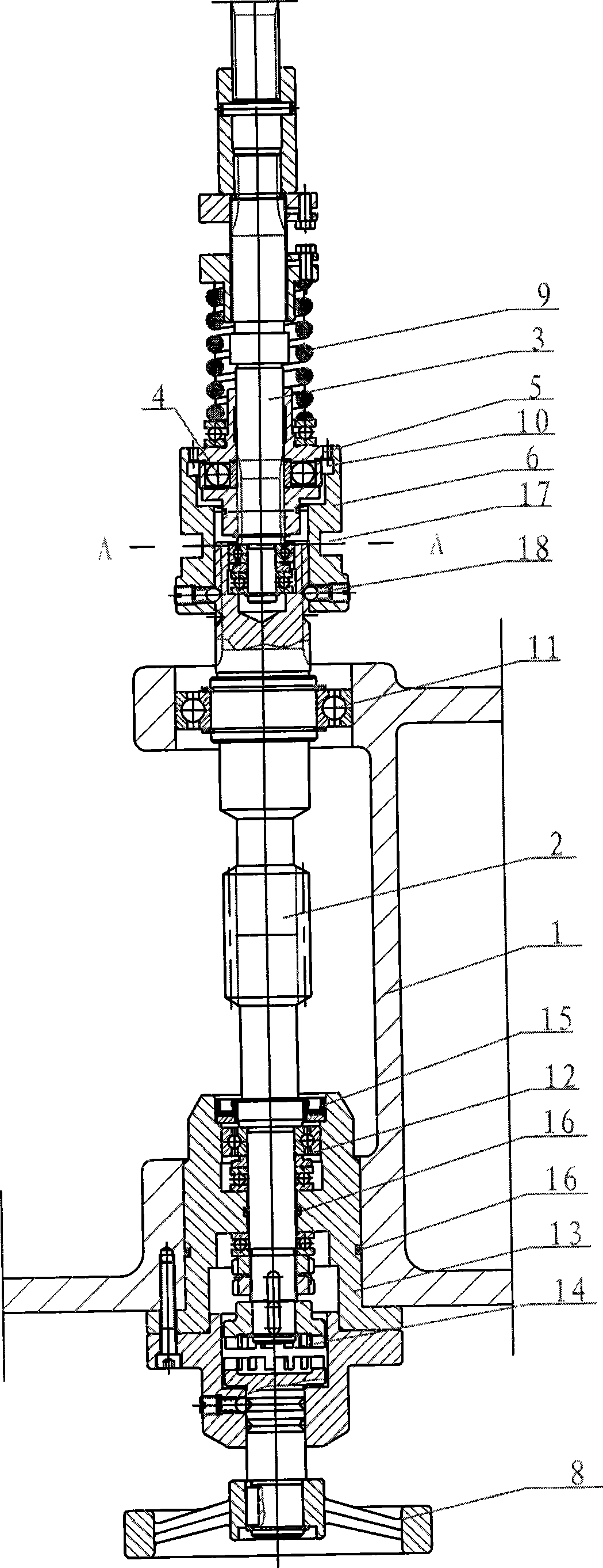
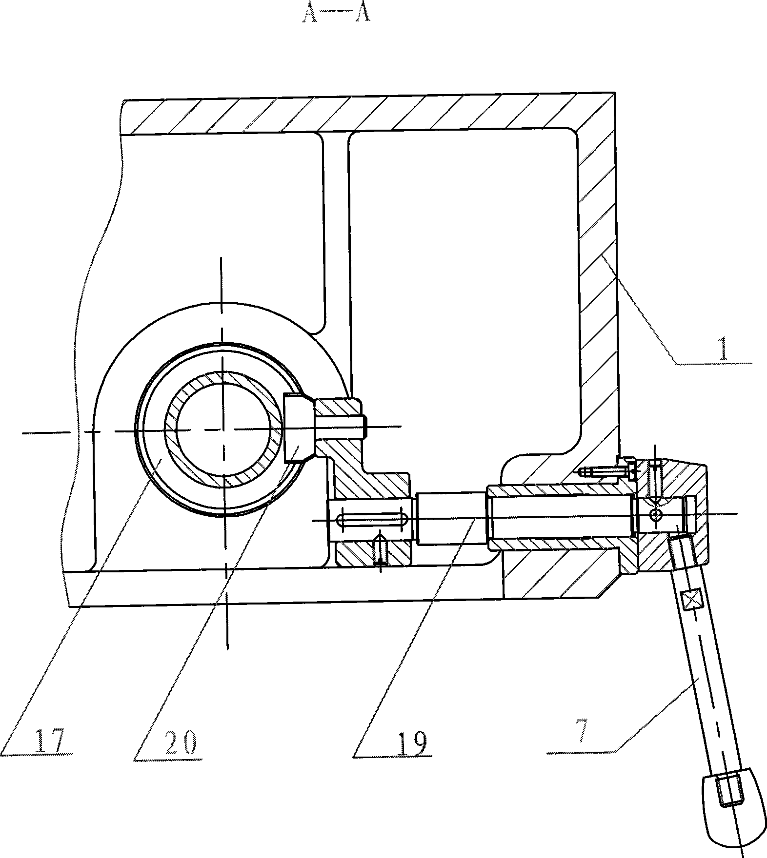
[0025] Such as Figures 2 to 4 As shown, the present invention is located in the right side of the spindle box 1 of the radial arm drilling machine, including the worm shaft 2, the spline shaft 3, the steel ball insurance clutch 4, the external gear 5, the internal gear 6, the handle 7 and the hand wheel 8, the The spline shaft 3 is sleeved and fixed with a spring 9, a steel ball insurance clutch 4 is provided between the spline shaft 3 and the external gear 5, the internal gear 6 has a tooth groove 10 matching the external gear 5, and the worm shaft 2 is a short solid shaft, the upper end of the worm shaft 2 is spline connected with the internal gear 6, the upper part is sleeved and fixed on the headstock 1 by the bearing I11, the lower part is connected with the headstock bearing seat 13 through the bearing II12, and the lower end is through the side The tooth clutch 14 is connected with the handwheel 8 . A rotary seal 15 is provided between the worm shaft 2 and the top of ...


PUM


Abstract

The invention relates to a worm shaft device of a radial drilling machine, which is arranged in the right side of a main shaft box (1) of the radial drilling machine and includes a worm shaft (2), a spline shaft (3), a steel ball safety clutch (4), an outer gear (5), an inner gear (6), a handle (7) and a handwheel (8); the spline shaft (3) is sheathed and fixed with a spring (9); the steel ball safety clutch (4) is arranged between the spline shaft (3) and the outer gear (5); the inner gear (6) is provided with a gear slot (10) which is matched with the outer gear (5); the worm shaft (2) is a short solid shaft; the upper end of the worm shaft (2) is connected with the spline of the inner gear (6); the upper part thereof is sheathed and fixed on the main shaft box (1) by a bearing I(11); the lower part thereof is connected with the bearing seat (13) of the main shaft box by a bearing II (12) and the lower end thereof is connected with the handwheel (8) by a side gear clutch (14). In the invention, the anti-leakage measures are improved; the structure is relatively simplified; the technique performances on processing and assembling are greatly improved; the handwheel can come way and stop rotating during power feed, thus eliminating the shaking and twinkling when the handwheel rotates and better showing a personalized design conception. The worm device can also be applied to a vertical drilling machine with a square-column or cylinder type.

Description

technical field [0001] The invention relates to a worm shaft device of a radial drilling machine. Background technique [0002] The feed system of the radial drilling machine is composed of two parts, the worm shaft and the horizontal shaft. Most of the current domestic radial drilling machines adopt the structure jointly designed by the industry in the 1960s. The worm shaft device of this structure is installed in the right side of the spindle box of the radial drilling machine. The worm shaft device transmits the transmission force obtained from the upper part of the box or the power obtained through the hand wheel to the horizontal axis through the worm gear pair, and then through the rack and pinion pair. The spindle moves linearly to complete the feed motion. The worm shaft device is an important device for manual micro-feeding by turning on the motorized feed of the spindle or disconnecting the motorized feed. The external gear 2' and the internal gear 3' of the devi...

Claims


Application Information

Patent Timeline
Patent Type & Authority Applications(China)
IPC IPC(8): B23B47/18B23B39/12
Inventor 王豫康龚建浩
Owner 南通西马特机器制造有限公司
Why Eureka
Try Eureka