Cleaning device for chemical mechanical polishing device

A cleaning device, chemical-mechanical technology, used in grinding/polishing equipment, grinding/polishing safety devices, cleaning methods using liquids, etc. Problems such as shortening polishing pad life

Active Publication Date: 2009-03-18
K C TECH
View PDF0 Cites 13 Cited by
  • Summary
  • Abstract
  • Description
  • Claims
  • Application Information

AI Technical Summary

Problems solved by technology

[0014] However, since the conventional cleaning device for CMP equipment sprays the cleaning liquid only in a single way, the speed of removing mud par

Method used


Image

  • Cleaning device for chemical mechanical polishing device
  • Cleaning device for chemical mechanical polishing device
  • Cleaning device for chemical mechanical polishing device

Examples


Embodiment Construction

[0024] Hereinafter, an exemplary embodiment according to the present invention will be described with reference to the accompanying drawings. In addition, it should be understood by those skilled in the art that various changes in form and details may be made within the scope of the present invention, but the scope of the present invention is not limited by the above-described embodiments. It is worth noting that in the drawings, the same parts are denoted by the same reference numerals.

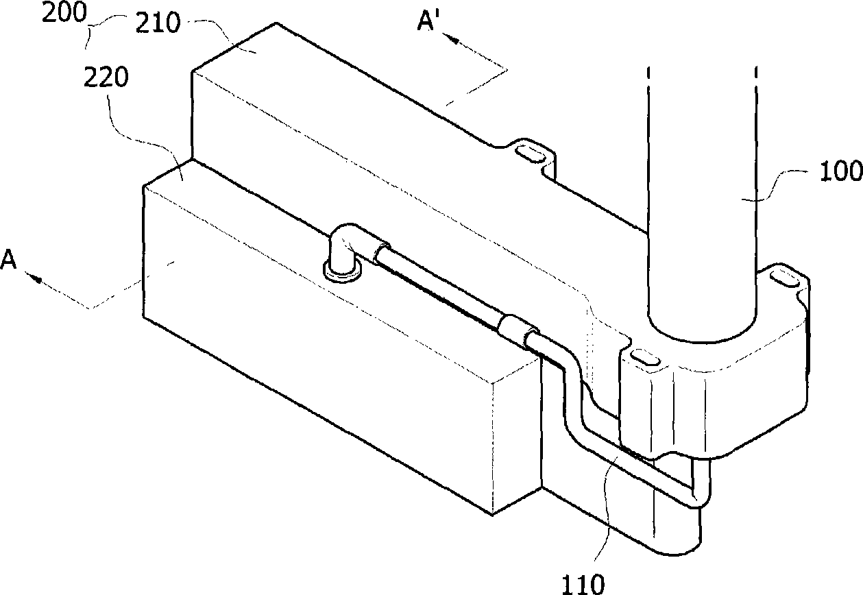
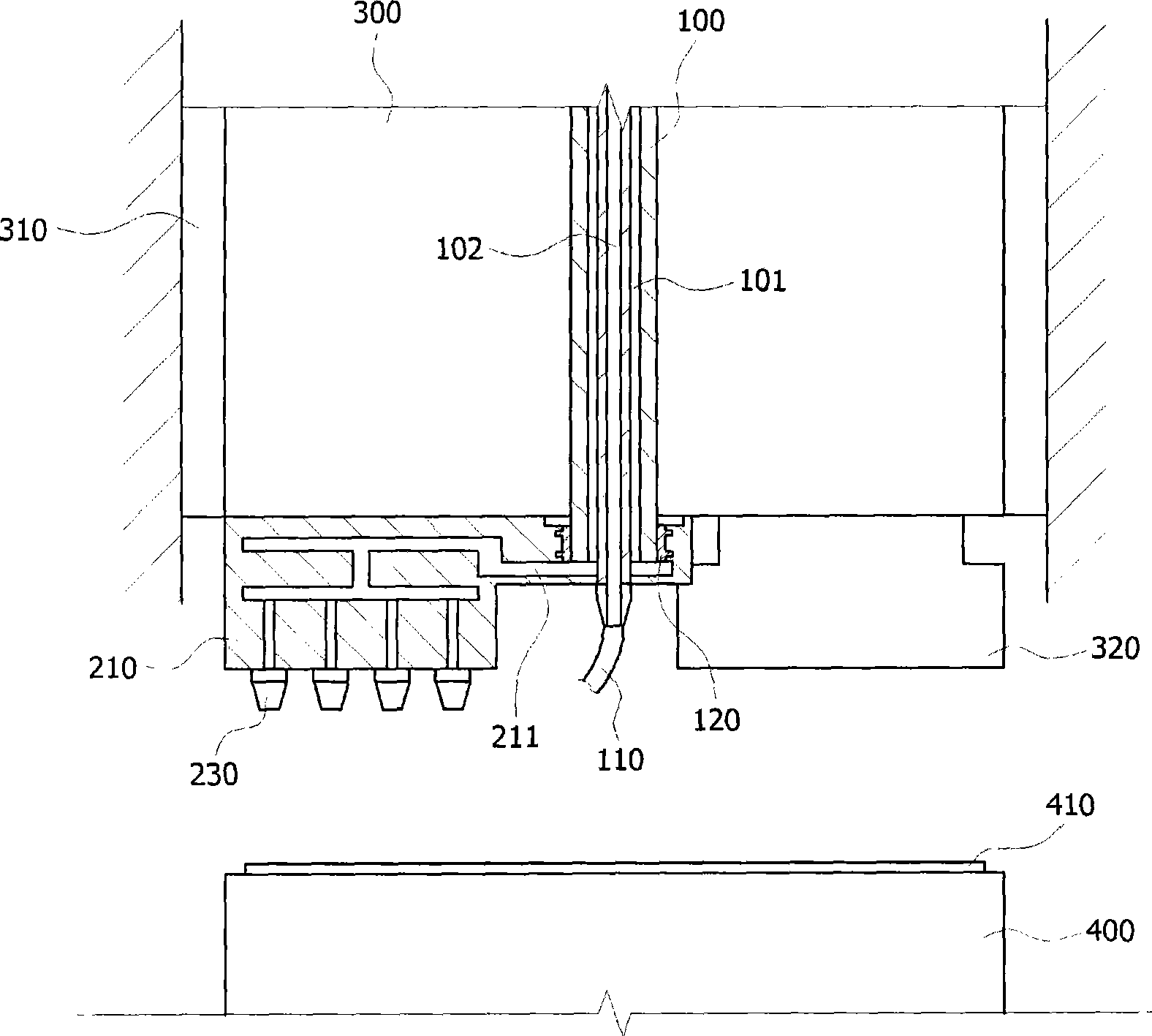
[0025] figure 2 is a schematic perspective view showing a cleaning device for a CMP apparatus according to an embodiment of the present invention; image 3 is a schematic sectional view of a CMP apparatus using a cleaning device for a CMP apparatus according to an embodiment of the present invention; Figure 4 is along figure 2 Schematic cross-sectional view of a cleaning device for a CMP apparatus taken along the center line A-A'.

[0026] refer to Figure 2 to Figure 4 According to a ...


PUM


Abstract

The invention discloses a cleaning device used in chemical mechanical equipment. The cleaning device comprises a non-rotatable central axis which is connected with a rotary main axis in a non-rotatable manner and a nozzle block; the non-rotatable central axis comprises a first channel and a second channel which are formed in the interior of the non-rotatable central axis; cleaning liquid flows into the first channel; a compressed gas flows into the second channel; the nozzle block is connected with the main axis so as to rotate around the non-rotatable central axis on a polishing pad; the nozzle block mixes the cleaning liquid provided by the first channel and the compressed gas provided by the second channel, thus forming two fluids; the mixed two fluids are sprayed on the polishing pad by pressure. Therefore, the cleaning liquid is pressurized and can be fast sprayed on the polishing pad, thereby being capable of completely removing mud particles and impurities from the polishing pad. Besides, the cleaning device can prevent a wafer from scratching and can also prolong the service life of the polishing pad.

Description

technical field [0001] The present invention relates to a cleaning device for a chemical mechanical polishing device, and more particularly, to a cleaning device for a chemical mechanical polishing device capable of removing impurities generated in a polishing pad of a polishing device performing a chemical mechanical polishing operation. Impurities including slurry particles prevent wafer scratches. Background technique [0002] Generally, a semiconductor element is manufactured by performing various processing processes such as a deposition process, a photographic process, an etching process, and an ion implantation process. [0003] For example, where a silicon wafer is processed with various processing layers, the process of selectively removing and patterning some of these processing layers and then depositing additional processing layers on the surface of the preformed processing layers can be repeated. [0004] Such processing layers may be insulating layers, gate ox...

Claims


Application Information

Patent Timeline
IPC IPC(8): B24B29/00B24B37/04B24B55/00H01L21/304B08B3/00B08B5/00
Inventor 孙准晧徐盛范
Owner K C TECH
Why Eureka
Try Eureka