Method for implementing sludge decrement by using municipal sewage pipe network

A technology for urban sewage and sludge reduction, applied in the direction of aerobic and anaerobic process treatment, can solve the problems of high equipment energy and operating costs, large floor area, high treatment costs, etc., to change the concept of sewage treatment, investment Small, low-cost effect

Active Publication Date: 2009-03-25
NAT ENG RES CENT OF URBAN WATER RESOURCE
View PDF0 Cites 10 Cited by
  • Summary
  • Abstract
  • Description
  • Claims
  • Application Information

AI Technical Summary

Problems solved by technology

[0003] The present invention solves the problem that the existing sludge treatment occupies a large area, pollutes a wide range, has high treatment costs, requires equipment, energy and operating costs for heat treatment to be very high, and the substances in the sludge will produce secondary pollution when burned, and the sewage Heavy metals, organic matter, N, P, etc. in mud may cause pollution to surface water and groundwater. A method of sludge reduction using urban sewage pipe network is provided. The specific technical solution to solve the above problems is as follows:

Method used


Image

  • Method for implementing sludge decrement by using municipal sewage pipe network

Examples


specific Embodiment approach 1

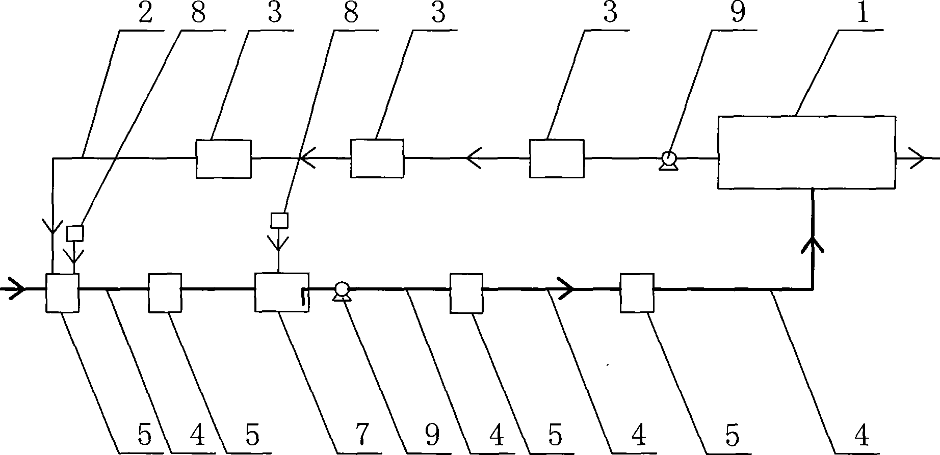
[0007] Specific implementation mode one: combine figure 1 The present embodiment will be described. In this embodiment, a sludge delivery pipeline 2 is set between the sewage treatment plant of the urban sewage pipe network and the inspection well, and a bioreactor 7 is arranged on the main pipe or the main pipe 4 of the urban sewage pipe network, and the inspection well 5 and the biological reaction Aeration is applied in the device 7, and the reduced sludge through the urban sewage pipe network main pipe or the main pipe 4 and the bioreactor 7 is input into the sewage treatment plant 1 for recycling.

specific Embodiment approach 2

[0008] Embodiment 2: The difference between this embodiment and Embodiment 1 is that it also includes a device 3 for pre-shredding microbial cells in the sludge in the sludge conveying pipeline 2 on the sludge conveying pipeline.

specific Embodiment approach 3

[0009] Specific embodiment three: the difference between this embodiment and specific embodiment two is that the pre-crushing treatment device 3 selects ultrasonic device, microwave device, ozone and / or ClO 2 Dosing device.

[0010] Ultrasonic crushing is used to break microbial cells by using the dispersion effect of ultrasonic waves in liquids to cause cavitation in liquids, thereby breaking solid particles or cell tissues in liquids. Ultrasonic waves will generate powerful pressure waves in the liquid, and this pressure wave will form millions of microscopic bubbles. With the high-frequency vibration, the bubbles will grow rapidly and then close suddenly. When the bubbles close, due to the collision between the liquids The powerful shock wave generates a pressure of thousands of atmospheres around it (that is, ultrasonic cavitation), and the energy is enough to break and reorganize cells and various inorganic substances. The sludge treated by ultrasonic waves is conducive ...


PUM


Abstract

The invention provides a method for implementing sludge reduction by taking advantage of a municipal sewage pipe network and relates to sludge reduction methods. The method solves the problems of large occupied land area, wide pollution range and high treatment expense caused by the existing sludge treatment. In the invention, a sludge transmission pipeline is arranged between a sewage treatment plant and an inspection pit of the municipal sewage pipe network, the microbial cells of the sludge in the sludge transmission pipeline are smashed; a bioreactor is arranged on an urban trunk sewer or trunk pipe, aeration is implemented in the inspecton pit and the bioreactor, and the sludge smashed and reduced by the bioreactor is input to the sewage treatment plant. Compared with a traditional urban sewage treatment method, the invention has low cost, small investment, high efficiency and good treatment effect, relieves the load of subsequent processing technology, reduces the volume of subsequent treatment structure and lowers engineering cost. In appropriate conditions, the sludge possibly has zero growth or even negative growth and can be effectively reduced.

Description

technical field [0001] The present invention relates to a method for sludge reduction. Background technique [0002] Sludge is solid waste produced during sewage treatment. With the development of sewage treatment, the total water volume and treatment degree of sewage treatment plants will continue to expand and improve, and the amount of sludge produced will also increase significantly. At the same time, the investment and operating costs of sludge treatment are huge, which can account for 25%-65% of the investment and operating costs of the entire sewage treatment plant, which has become a heavy burden for urban sewage treatment plants. The usual practice of sludge treatment is: after pretreatment such as concentration, stabilization, dehydration, etc., the final disposal is carried out. At present, the newly generated sludge in sewage treatment plants generally has a high water content and a large volume, and must be concentrated and dehydrated before corresponding trea...

Claims


Application Information

Patent Timeline
IPC IPC(8): C02F3/30
Inventor 马军王群韩雅红韩帮军
Owner NAT ENG RES CENT OF URBAN WATER RESOURCE
Why Eureka
Try Eureka