
Uplink (reverse link) power control method for radio communication system

A wireless communication system and power control technology, applied in transmission control/balance, sustainable communication technology, advanced technology, etc., can solve problems such as poor cell edge performance, impact on overall system performance, and fewer users sending data, etc., to achieve Optimize the system and improve the overall performance

Inactive Publication Date: 2009-04-01
BEIJING UNIV OF POSTS & TELECOMM
View PDF0 Cites 24 Cited by
  • Summary
  • Abstract
  • Description
  • Claims
  • Application Information

AI Technical Summary

Problems solved by technology

The previous full power transmission method (all) will lead to poor cell edge performance, because full power transmission means that edge users (mobile stations) will cause a lot of interference to other cell users (mobile stations)
However, the traditional power control scheme (completely compensating for path loss and shadow fading) will affect the overall performance of the system, because in this case, the maximum transmit power of edge users (mobile stations) and center users (mobile stations) will be With different degrees of reduction, the number of users (mobile stations) sending data at a high data rate will be relatively small, and the system spectrum utilization rate will be low
[0006] In summary, it can be seen that the previous power control methods cannot well guarantee the performance of the edge users (mobile stations) in the system, and even affect the transmission power and transmission data rate of the central users (mobile stations), so that they cannot be very good. Good guarantee of overall system performance

Method used


Image

  • Uplink (reverse link) power control method for radio communication system
  • Uplink (reverse link) power control method for radio communication system
  • Uplink (reverse link) power control method for radio communication system

Examples


Embodiment Construction

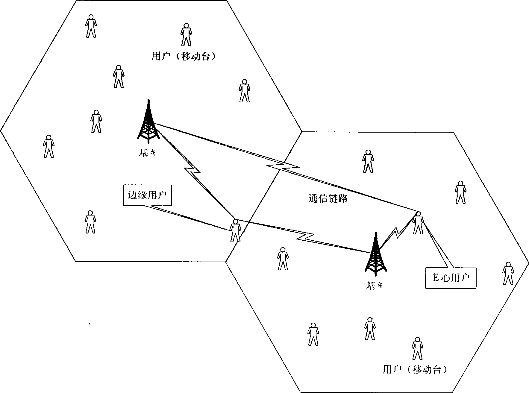
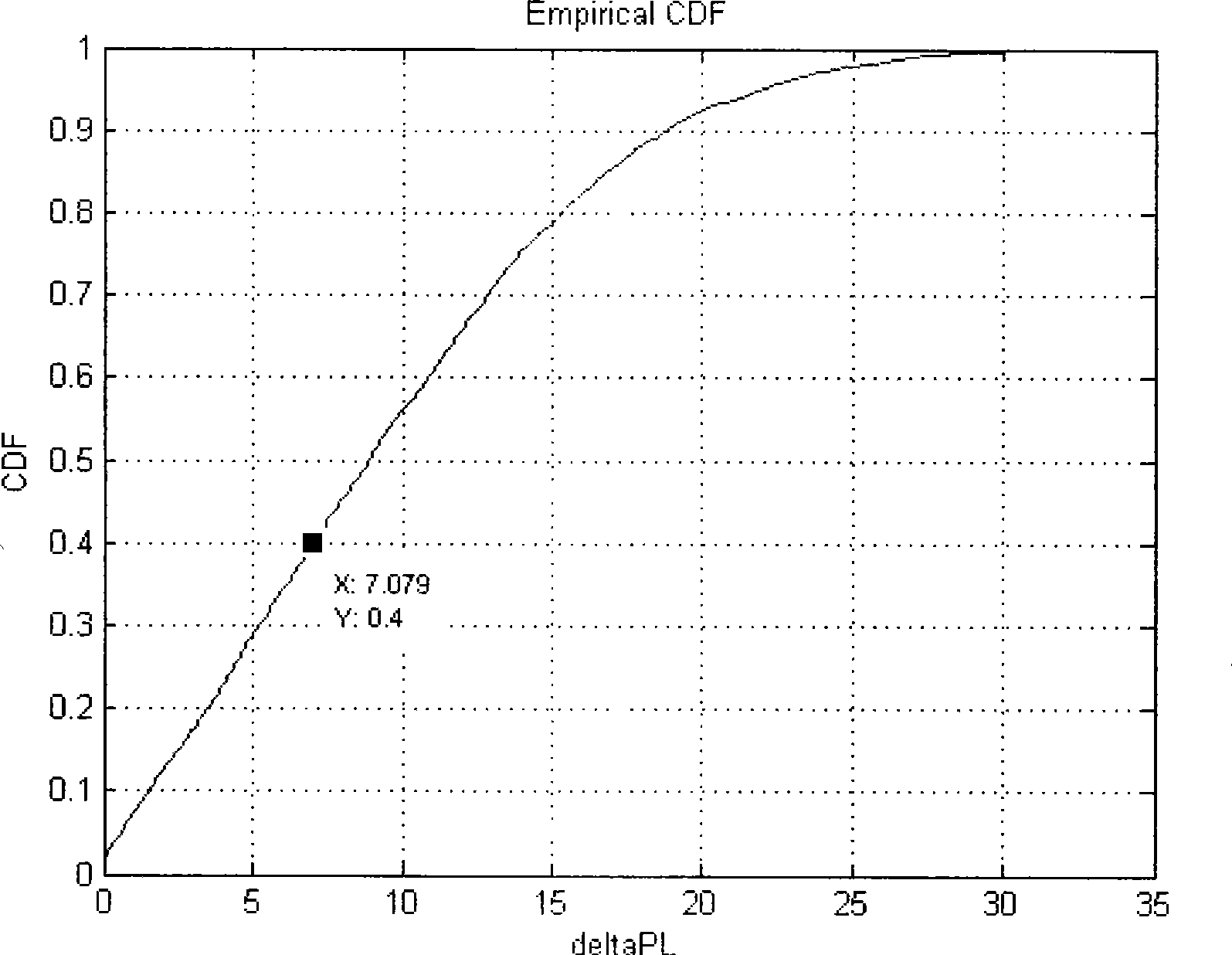
[0032] This method is an open-loop partial power control method, for different α and different ΔPL th , the system behaves differently. figure 1 It is a schematic diagram of a scenario of the power control method, assuming a cell of a cellular mobile communication system.

[0033] The implementation of this method is roughly divided into two steps:

[0034] 1. According to the user (mobile station) information measured by the downlink pilot, set ΔPL th value.

[0035] 2. The user (mobile station) adjusts its transmission power according to the above information, and performs power control.

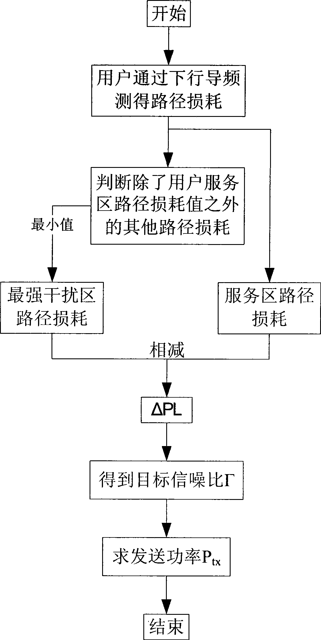
[0036] Taking a user (mobile station) at a certain moment in the system as an example, the following is the specific algorithm flow, assuming that α is a fixed value, such as figure 2 :

[0037] 1. According to the distribution of system users (mobile stations) at the current moment, use the downlink pilot channel to measure the path loss value (or large-scale fading value, including...


PUM


Abstract

The invention provides a power control method in an uplink (a reverse link) of a wireless communication system. The core of the method is as follows: a user (a mobile station ) dynamically carries out power control and adjusts transmission power by path loss (or large scale fading value comprising path loss, shadowing fading, serial gain, penetration loss)measured by a DwPTS and by the different value of path loss between the strongest interference zone and a service zone. The method provided by the invention dynamically adjusts power control parameters, carries out power control and adjusts emission power of the user (the mobile station) according to a position of the user, appropriately reduces emission power of marginal users, thus reducing interference generated by the marginal users (the mobile station), optimizes the resource efficiency of a system and improves the performance of the system under the premise of not losing fairness.

Description

technical field [0001] The present invention relates to the technical field of wireless communication, in particular to a power control method in the uplink (reverse link) of a wireless communication system. Background technique [0002] Power control in wireless communication (referred to as power control) can be divided into two categories: inner loop power control and outer loop power control. Inner loop power control can be divided into open loop and closed loop. The open-loop method generally uses the uplink interference to estimate the downlink, or estimates the uplink based on the downlink, and is not closed; while the closed-loop method has a feedback loop and is closed. [0003] The main purpose of power control is to allow each transmitter to obtain satisfactory call quality with appropriate power in the current wireless environment, while minimizing interference. In the uplink (reverse) link random access stage, the path loss value (or large-scale fading value, ...

Claims


Application Information

Patent Timeline
IPC IPC(8): H04B7/005
CPCY02B60/50Y02D30/70
Inventor 邱禹冯春燕曾志民张天魁
Owner BEIJING UNIV OF POSTS & TELECOMM
Learn More