Semi-automatic layout machine

A spreader, semi-automatic technology, applied in the direction of AC motor control, AC motor direction control, motor generator/starter, etc. , The effect of reducing work intensity and improving work efficiency

Inactive Publication Date: 2009-04-08
DONGYING TANSIS TEXTILE
View PDF0 Cites 5 Cited by
  • Summary
  • Abstract
  • Description
  • Claims
  • Application Information

AI Technical Summary

Problems solved by technology

[0002] The original cloth spreading machine used four people to push the cloth, the cloth spreading spee...

Method used


Image

  • Semi-automatic layout machine
  • Semi-automatic layout machine

Examples


Embodiment Construction

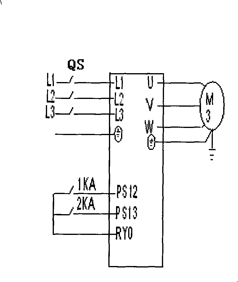
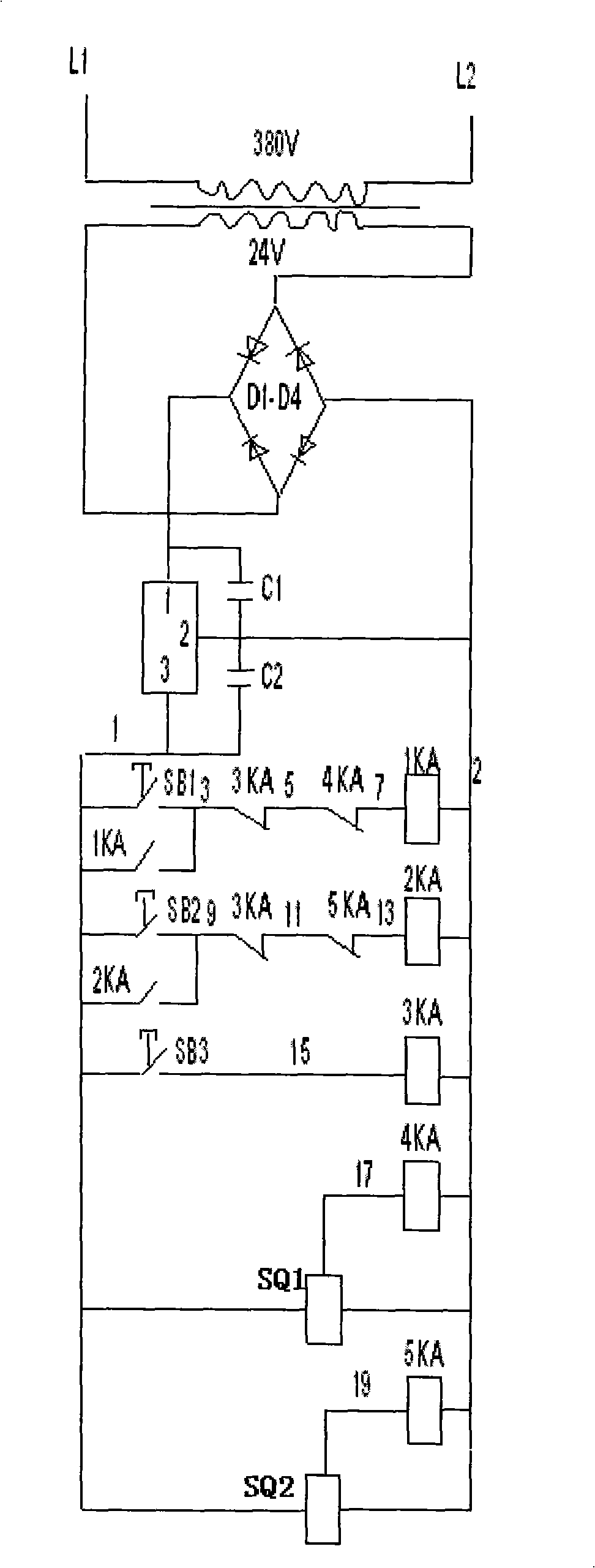
[0008] combined with figure 1 with 2 , to further describe the present invention:

[0009] Install a control box on one side of the original spreading machine, place circuit breakers, transformers, general relays, buttons and rectification and voltage stabilization devices in the control box, and install frequency converters, motors and proximity switches on the other side, and connect the proximity switches and Connect 4KA and 5KA in the control box, connect the forward and reverse start signals of the frequency conversion to 1KA and 2KA in the control box, and connect the output terminals U, V and W of the frequency converter to the motor respectively.

[0010] When it needs to run in the forward direction, press the start button SB1, the 1KA coil is energized and closed, the 1KA normally open contact is closed and self-protected, the other 1KA normally open contact is closed, and the RYO and PS12 are connected to the inverter to run forward signal, the motor runs forward....


PUM


Abstract

The invention relates to a cloth laying machine used for producing household textile products, in particular to a semi-automatic cloth laying machine. The technical proposal is that the cloth laying machine comprises an original cloth laying machine, and the cloth laying machine is characterized in that one side of the original cloth laying machine is provided with a control box in which a circuit breaker, a transformer, a general purpose relay, push buttons and a rectifying and voltage stabilizing device are arranged, the other side of the original cloth laying machine is provided with a frequency converter, a motor and a proximity switch, the proximity switch (SQ) is connected with 4KA and 5KA arranged in the control box, a forward enabling signal and a backward enabling signal of the frequency converter are connected with 1KA and 2KA arranged in the control box, and output terminals U, V and W of the frequency converter are respectively connected with the motor. The cloth laying machine has the beneficial effects that the improved cloth laying machine has stable performance, is safe and reliable, improves the speed, greatly improves the working efficiency, reduces labor and reduces working intensity; lay cloth orderly, stably and uniformly, meets the process requirements and guarantees the product quality.

Description

1. Technical field: [0001] The invention relates to a home textile spreading machine, in particular to a semi-automatic spreading machine. 2. Background technology: [0002] The original cloth spreading machine used four people to push the cloth, the cloth spreading speed was too slow, the efficiency was too low, too many people were employed, and the work intensity was too high. . 3. Contents of the invention: [0003] The purpose of the present invention is to provide a semi-automatic spreader for the above-mentioned defects in the prior art, which is easy to operate, flexible and durable, and has a wide range of speed regulation. [0004] The technical solution is: including the original spreading machine, which is characterized in that a control box is installed on one side of the original spreading machine, and circuit breakers, transformers, general relays, buttons and rectifying and voltage stabilizing devices are placed in the control box, and the other Install t...

Claims


Application Information

Patent Timeline
IPC IPC(8): G05B19/04H02P1/26H02P27/04B65H47/00H02P23/24
Inventor 杨金村张吉祥
Owner DONGYING TANSIS TEXTILE
Why Eureka
Try Eureka