

Controller for electric vehicle
A technology of electric vehicle controller and cruise control, which is applied in electric vehicles, electronic commutation motor control, control driving, etc., can solve problems such as inconvenience of use and inability to start the motor, and achieve convenient use, ensure reliability, and good anti-theft function. Effect
- Summary
- Abstract
- Description
- Claims
- Application Information
AI Technical Summary
Problems solved by technology
Method used
Image

Examples
Embodiment 1
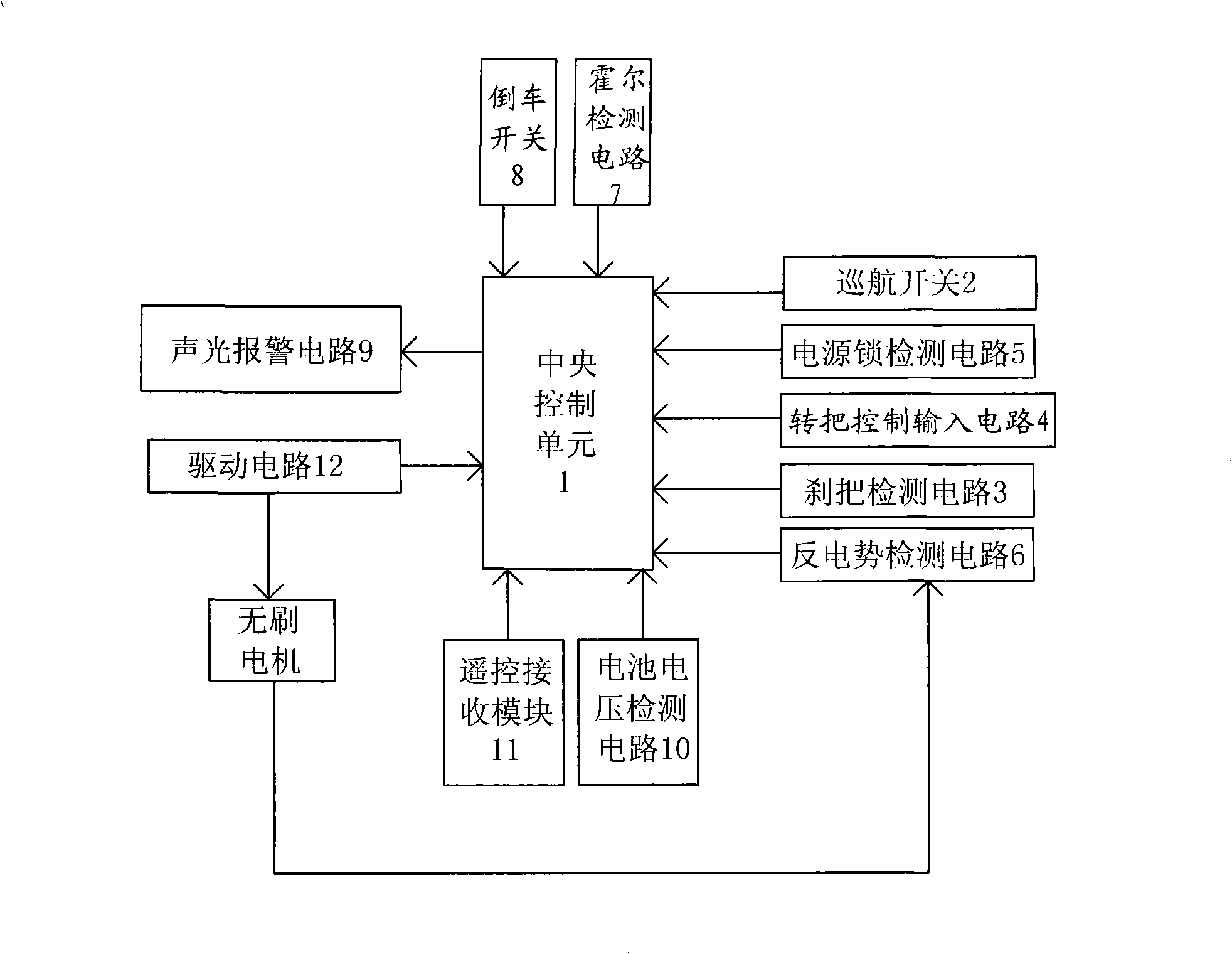
[0021] See figure 1 -2. The electric vehicle controller in this embodiment includes: a central control unit 1, a cruise switch 2, a brake handle detection circuit 3, a handlebar control input circuit 4, a power lock detection circuit 5, a back EMF detection circuit 6, and a Hall detection circuit Circuit 7, reversing switch 8, sound and light alarm circuit 9, battery voltage detection circuit 10, remote control receiving module 11 and drive circuit 12 for controlling the rotation of the brushless motor.
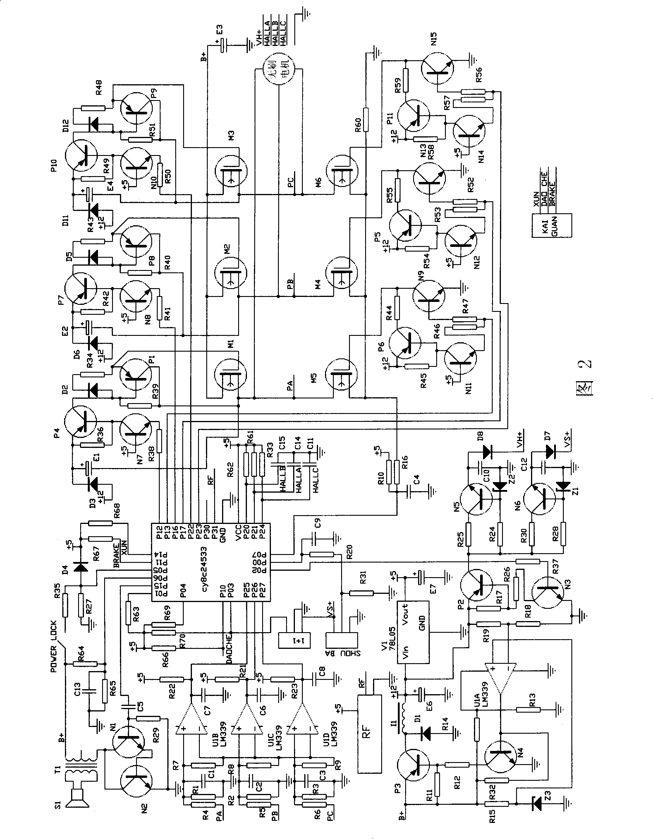
[0022] The central control unit 1 adopts a single-chip microcomputer whose model is cy8c24533, and the driving circuit 12 is connected with the motor control output terminal of the central control unit 1 (that is, the P12-13, P16-17 and P22-23 pins of the single-chip microcomputer), and the handle control input circuit 4 is connected with the The speed control input terminal of the central control unit 1 (ie, the P00 pin of the single-chip microcomputer) is connected, and the...
PUM
 Abstract
Description
Claims
Application Information