
Motor-pump assembly for household appliances

A technology for household appliances and electric pumps, applied in electric components, electrical components, machines/engines, etc., to achieve the effect of large heat exchange area and effective heat treatment

Active Publication Date: 2009-04-15
阿思科控股有限公司
View PDF3 Cites 4 Cited by
  • Summary
  • Abstract
  • Description
  • Claims
  • Application Information

AI Technical Summary

Problems solved by technology

This, disadvantageously, requires the use of large pole shoes and bifurcations and large area helical coils to obtain a low reluctance magnetic circuit in order to carry high flux

Method used


Image

  • Motor-pump assembly for household appliances
  • Motor-pump assembly for household appliances
  • Motor-pump assembly for household appliances

Examples


Embodiment Construction

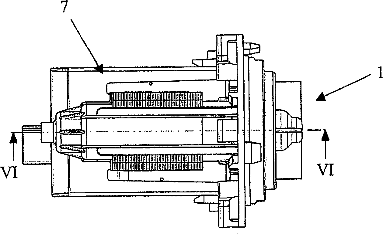
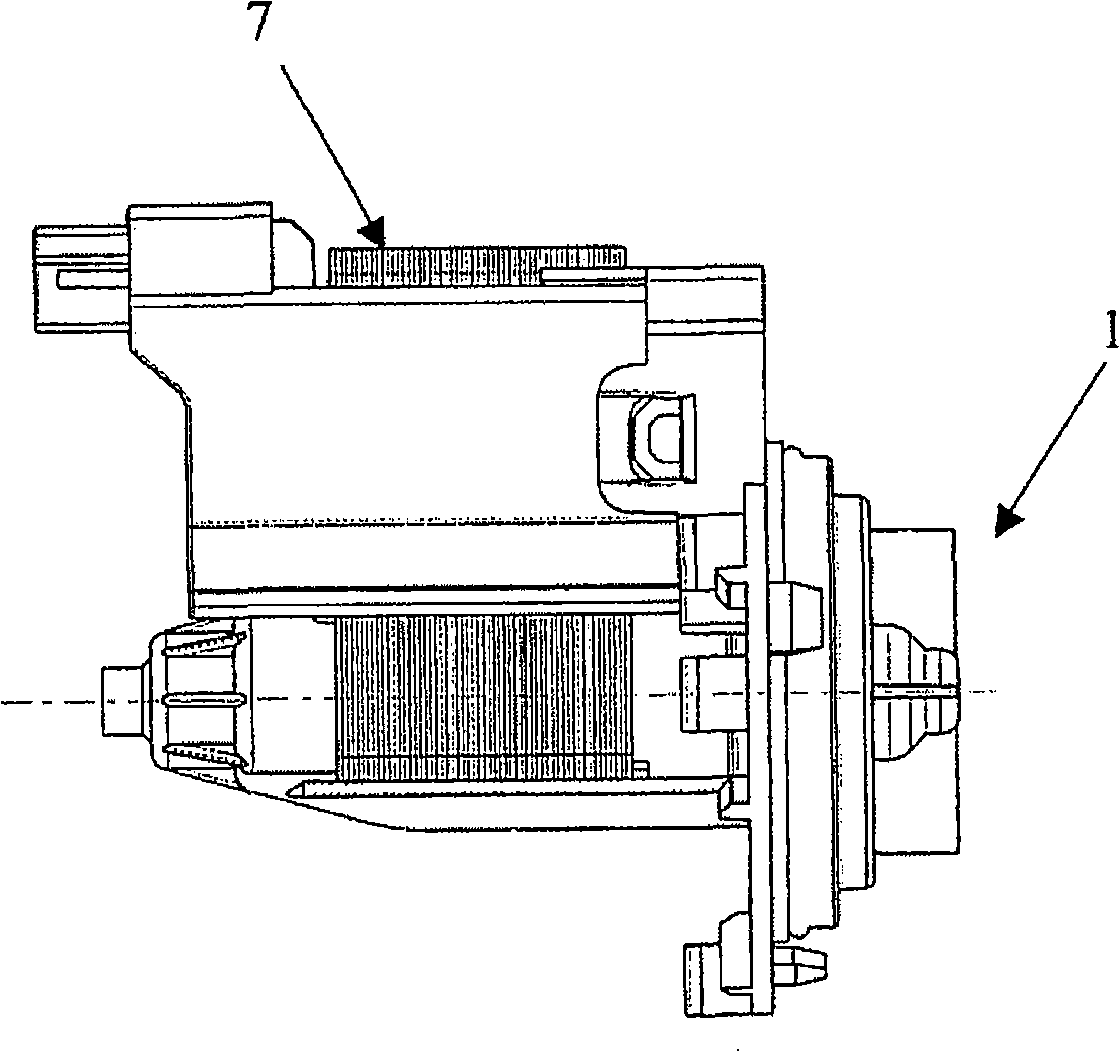
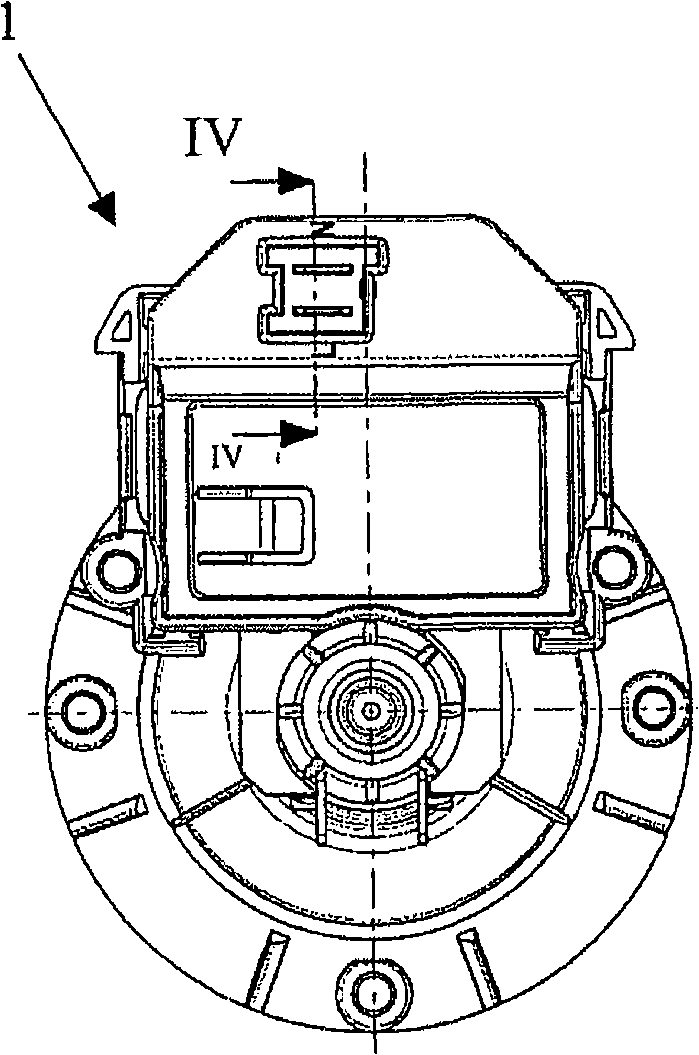
[0027] refer to Figure 1-7 , shows the electric pump assembly 1 of the present invention. The electric pump assembly 1 is made up of a pump body and a one-way synchronous motor 7, wherein the pump body only clearly shows the impeller, because other components have no effect on clearly describing the present invention, and the one-way synchronous motor has a permanent magnet Internal rotor.

[0028] The impeller 2A is connected to the rotor 3 of the single-phase synchronous motor 7 through a shaft 2B. An overmould 3A is fixedly connected to said rotor 3 . The impeller 2A, shaft 2B, rotor 3 and overmold 3A can rotate coaxially.

[0029] It can be seen that the bearings 9, 10 support the shaft 2B, and thus the rotor 3, in such a way that they can rotate.

[0030] The rotor 3 is a permanent magnet. The rotor is separated by an air gap 4 from a tuning-fork-type (sometimes called fork-type) stator 5, which is a ferromagnetic core. The stator 5 is formed by stacking U-shaped l...


PUM


Abstract

The assembly (1) has a pump equipped with an impeller, and a single-phase synchronous electric motor (7) connected with a mechanical start-up. The start-up is equipped with a stator and a rotor that are mutually separated by an air gap, where the rotor is of a type that utilizes permanent magnets, and the stator is of a diapason type. The stator is equipped with a pack core of laminations and a pair of pole pieces that wrap coaxially around the rotor, where length of the pieces is 15 percentage less than length of the rotor. Reels of aluminum wire are wound around the stator.

Description

technical field [0001] The object of the present invention is to provide an electric pump assembly for household appliances such as dishwashers and washing machines, especially for draining water, which electric pump assembly includes a pump body equipped with an impeller and a single-phase synchronous motor , the single-phase synchronous motor is equipped with a stator and a rotor separated from each other by an air gap formed by a machine, the rotor is a permanent magnet rotor, the stator is a tuning fork (diapason) type, and the stator is equipped with a laminated core and a pair of pole pieces coaxially surrounding the rotor. Background technique [0002] It is well known that it is necessary to manufacture an electric pump drainage device for household appliances such as washing machines and dishwashers in order to obtain the best benefit, i.e., to obtain the hydraulic operating speed of the pump (fluid pressure or flow rate) and the Optimum ratio between the electrica...

Claims


Application Information

Patent Timeline
Patent Type & Authority Applications(China)
IPC IPC(8): H02K1/12H02K1/22H02K15/02H02K7/14
CPCF04D13/064H02K7/14H02K21/185F04D13/0606F04D13/06F04D13/08
Inventor 埃利奥·马里斯
Owner 阿思科控股有限公司
Learn More