
Metal / ceramic microlaminate material and preparation thereof

A laminated material and ceramic microtechnology, applied in the field of material science, can solve the problems of low strength of metal sheets, brittle fracture of columnar grain boundaries, etc.

Inactive Publication Date: 2009-04-22
HARBIN INST OF TECH
View PDF0 Cites 15 Cited by
  • Summary
  • Abstract
  • Description
  • Claims
  • Application Information

AI Technical Summary

Problems solved by technology

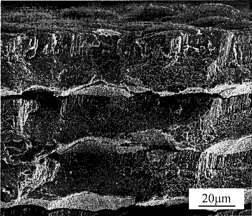
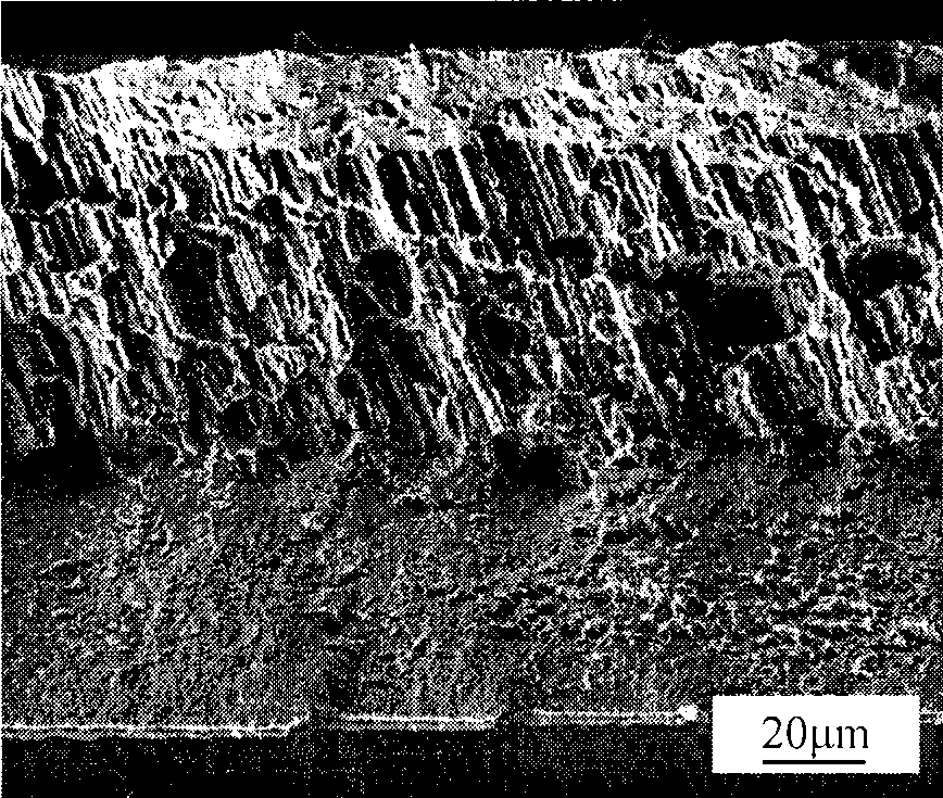
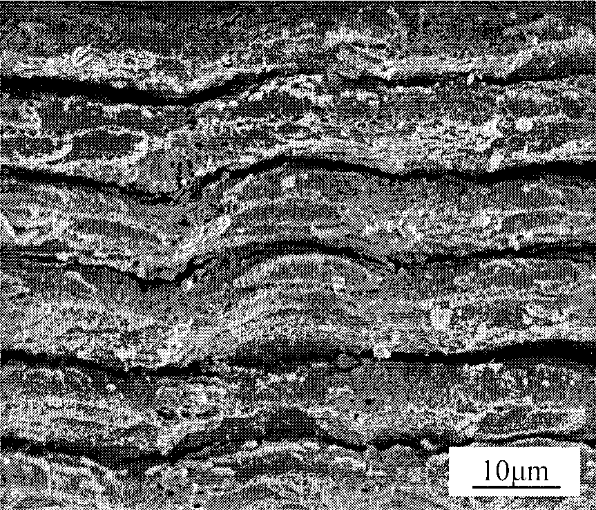
[0003] The object of the present invention is to provide a kind of solution EB-PVD sheet metal intensity is low, the brittle fracture problem that easily occurs along the columnar grain boundary, improve the metal / ceramic micro-lamination material and the its preparation method

Method used


Image

  • Metal / ceramic microlaminate material and preparation thereof
  • Metal / ceramic microlaminate material and preparation thereof
  • Metal / ceramic microlaminate material and preparation thereof

Examples


Embodiment 1

[0015] Embodiment 1, combining figure 1 , figure 2 , the preparation method of the metal / ceramic micro-laminated material of the present invention, one of the process:

[0016] (1) Vacuuming: Polish the surface of the φ1000mm substrate, and ultrasonically clean it in acetone for 10 minutes, dry it and connect it to the vertical rotating shaft at the top of the working chamber. Place the NiCoCrAl target and the YSZ target in two crucibles respectively. After placing them properly, evacuate to 10 -3 Pa.

[0017] (2) Heating the substrate: use a radiant heater to heat the substrate to above 500°C, and discharge the gas adsorbed on the substrate. Then the temperature of the substrate and the degree of vacuum are adjusted by means of intermittent heating. The vacuum is stable at 10 -3 ~10 -2 After Pa, stabilize the substrate temperature within the range of 650±20°C. At the same time, the rotation speed of the substrate is controlled by the motor to be 6 rpm.

[0018] (3) D...

Embodiment 2

[0022] Example 2, combined with figure 1 , figure 2 , image 3 , the preparation method of the metal / ceramic micro-laminated material of the present invention, process two:

[0023] (1) Vacuuming: Polish the surface of the φ1000mm substrate, and ultrasonically clean it in acetone for 10 minutes, dry it and connect it to the vertical rotating shaft at the top of the working chamber. Place the NiCoCrAl target and the YSZ target in two crucibles respectively. After placing them properly, evacuate to 10 -3 Pa.

[0024] (2) Heating the substrate: use a radiant heater to heat the substrate to above 500°C, and discharge the gas adsorbed on the substrate. Then the temperature of the substrate and the degree of vacuum are adjusted by means of intermittent heating. The vacuum is stable at 10 -3 ~10 -2 After Pa, stabilize the substrate temperature within the range of 650±20°C. At the same time, the rotation speed of the substrate is controlled by the motor to be 6 rpm.

[0025]...


PUM

PropertyMeasurementUnit
Tensile strength at room temperatureaaaaaaaaaa
Tensile strengthaaaaaaaaaa

Abstract

The invention provides a metal / ceramic micro-lamination material and a preparation method thereof. The method adopts an electron beam physical vapor deposition technology and alternately evaporates a metal target material and a ceramic material through an electron gun to prepare the metal / ceramic micro-lamination material. The thickness of a ceramic layer is 1 mu m; and the thickness of a metal layer is between 10 and 35 mu m, and the volume fraction ratio of the metal layer and the ceramic layer, namely the thickness ratio or the thickness ratio of layers is between 10 and 35. The metal target material is Ni-20Co-12Cr-4Al (weightt percent); and the ceramic target material is ZrO2(YSZ) containing 8 weight percent of Y2O3. The metal / ceramic micro-lamination material has large thickness ratio of layers; therefore, the material can keep the characteristic of good toughness of the metal material to a great extent. Simultaneously, the existence of a lamination structure limits the growth of columnar crystals in the metal layer and reduce the possibility that crack expands along the metal grain boundary. Compared with a monolayer EB-PVD metal sheet, the metal layer of the micro-lamination material has less probability of brittle intergranular fracture and higher strength.

Description

(1) Technical field [0001] The invention relates to material science, specifically a metal / ceramic micro-laminate material and a preparation method thereof. (2) Background technology [0002] The Electron Beam Physical Vapor Deposition (EB-PVD) process is an evaporation method using electron beams as the heat source, which can evaporate almost all substances. It has the characteristics of high deposition rate, high thermal efficiency and low pollution in the preparation process. Therefore, it has been used as a method for preparing metal sheets at present. Usually, the EB-PVD film forms an equiaxed crystal structure in the early nucleation stage of the deposited material, and thereafter, as the film thickness increases, the columnar crystal structure becomes more and more obvious. Many studies have shown that the columnar crystal structure of PVD films usually contains many larger intercrystalline pores. Even if the porosity between these columnar grains can be reduced by...

Claims


Application Information

Patent Timeline
IPC IPC(8): C23C14/28C23C14/14C23C14/08B32B15/04B32B18/00
Inventor 梁军史国栋陈贵清
Owner HARBIN INST OF TECH
Learn More