Subsection rotating multi-head spring type self-cleaning reinforced heat exchanger

A heat-enhancing, spring-type technology, used in cleaning heat transfer devices, rotating equipment cleaning, heat transfer modification, etc., can solve problems such as large flow resistance, poor cleaning and descaling effects, and limited heat transfer enhancement effects. , to achieve the effect of strengthening convection heat transfer in the tube, good cleaning and descaling effect, and good cleaning and descaling effect.

Inactive Publication Date: 2010-04-14
TSINGHUA UNIV +1
View PDF1 Cites 0 Cited by
  • Summary
  • Abstract
  • Description
  • Claims
  • Application Information

AI Technical Summary

Problems solved by technology

"Rotor-type self-cleaning enhanced heat transfer device" (China Patent No.: 200520127121.9) adopts a segmented axial fixation method, which disperses the force of the fluid on the rotating rotor, thereby basically eliminating the impact of the fluid on the long spiral bond / piece / Due to the large force of the rotor, it is more prone to failure problems, but there are still problems such as the increase of flow resistance is too large
Rotating coil spring descaling method, the long coil spring is hung at the inlet of the heat exchange tube through a rotatable structure, and the rotating structure is prone to failure due to the large force of the fluid on the long coil spring; the single-head coil spring The thread pitch is relatively small, and due to the consideration of strength, the diameter of the spring wire is relatively large, so the increase in flow resistance is also relatively large and significant, usually the resistance increases by 3-10 times
The reciprocating coil spring descaling method has limited anti-scaling and descaling effects, and sometimes it is even prone to clogging when the scaling is relatively serious; at the same time, the reciprocating coil spring is a single-head coil spring, and there are also problems similar to the above-mentioned large flow resistance. insufficient
The current online rubber ball cleaning technology is widely used in power plant condensers, but the rubber balls currently used are microporous and soft elastomer structures, and it is difficult to accurately control the wet diameter and specific gravity of the rubber balls during use. It is also easy to be attached by sludge, dirt and microorganisms, resulting in unsatisfactory cleaning and descaling effects, low ball collection rate, easy to block pipes and other problems; rubber ball cleaning has almost no effect of strengthening convective heat transfer
To sum up, the current cleaning and descaling technologies have certain deficiencies, such as relatively large flow resistance, poor cleaning and descaling effects, limited effect of enhanced heat transfer, and prone to failures, etc., which affect their popularization and application.

Method used


Image

  • Subsection rotating multi-head spring type self-cleaning reinforced heat exchanger
  • Subsection rotating multi-head spring type self-cleaning reinforced heat exchanger
  • Subsection rotating multi-head spring type self-cleaning reinforced heat exchanger

Examples


Embodiment 1

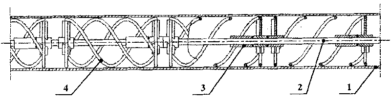
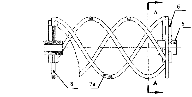
[0040] Such as figure 1As shown, the segmented rotating multi-head spring type self-cleaning enhanced heat exchange device of the present invention includes: a support frame installed at both ends of the heat exchange tube 1 (the heat exchange tube shown in the figure is a partial diagram after sectioning, and the support frame is used as a conventional technology not shown), two ends of the flexible shaft 2 fixed on the support frame, a plurality of axial positioning sleeves 3 sleeved and fixed on the flexible shaft 2, and a plurality of sleeves on the flexible shaft and can rotate around the flexible shaft 2 The self-rotating rotor 4 and other components. exist figure 1 There are four self-rotating rotors 4 in the cut-away partial heat exchange tube shown in , and the self-rotating rotors can be adjacent to each other or have gaps.

[0041] The axial positioning sleeve 3 is fixed on the flexible shaft 2, usually next to the self-rotating rotor, and the axial positioning sl...

Embodiment 2

[0055] Figure 9 It is a structural schematic diagram of Embodiment 2 of the present invention. exist Figure 9 Among them, 1 is a heat exchange tube (the heat exchange tube shown in the figure is a cutaway view), 2 is a flexible shaft with both ends fixed, 3 is an axial positioning sleeve, and 10 is a self-rotating rotor. The difference between this embodiment and the above-mentioned embodiments is that the self-rotating rotor of this embodiment has a double-rotation network multi-head spring structure, while the first embodiment has a single-rotation multi-head spring structure.

[0056] Figure 10 It is a structural schematic diagram of the self-rotating rotor in Embodiment 2 of the present invention, Figure 11 yes Figure 10 C-C section view. exist Figure 10 with Figure 11 Among them, 6 is a rotating blade, 8 is a connecting ring, 9 is a rotating sleeve, and 11 is a multi-head spring group with a bidirectional mesh structure. The rotating shaft sleeve 9 and the ...

Embodiment 3

[0061] Figure 13 It is a structural schematic diagram of Embodiment 3 of the present invention. exist Figure 13 Among them, 1 is a heat exchange tube (the heat exchange tube shown in the figure is a cutaway view), 2 is a flexible shaft with both ends fixed, 3 is an axial positioning sleeve, and 12 is a self-rotating rotor. The difference between this embodiment and the above-mentioned embodiments is: the self-rotating rotor of this embodiment is that one end of the multi-headed spring is connected to the rotating shaft sleeve, and the other end is in a free state, while the multi-headed spring of the first and second embodiments Both ends are connected to each other as a whole. Compared with Embodiment 1 and Embodiment 2, the flow resistance of this embodiment is smaller.

[0062] Figure 14 It is a structural schematic diagram of the self-rotating rotor in Embodiment 3 of the present invention, Figure 15 yes Figure 14 The D-D section view. exist Figure 14 with ...


PUM


Abstract

A sectional rotation multi-head spring self-cleaning reinforced heat exchange device belongs to the technical field of self-cleaning reinforced heat exchange. The heat exchange device is characterizedin that each autogyration rotor comprises at least one rotation driving impeller and a spring assembly which can be driven by fluid in pipes to rotate around a soft shaft; the rotation driving impeller comprises a rotation shaft housing sheathed on the soft shaft, the spring assembly is connected with the rotation shaft housing into a whole and rotates around the soft shaft along with the rotationshaft housing; the spring assembly comprises at least two springs which clean and decontaminate the inner wall of the heat exchange tube and reinforces heat exchange in rotation; the rate value of th e equivalent diameter of the spring section of the spring assembly to the inner diameter of the heat exchange tube ranges from 1% to 15%; the rate value of the spring thread pitch of the spring assembly to the inner diameter of the heat exchange tube ranges from more than 0.4. The heat exchange device has the advantages of small flow resistance, good cleaning and decontaminating effect, marked reinforced convection heat transfer effect, long service life, etc.

Description

technical field [0001] The invention belongs to the technical field of self-cleaning enhanced heat exchange, in particular to a multi-head spring type self-cleaning enhanced heat exchange device installed in a heat exchange tube and rotating around a rotating shaft in sections under the action of fluid in the tube. Background technique [0002] Shell-and-tube heat exchangers are widely used in electric power, chemical industry, petroleum and other industrial fields. Most of the heat exchangers have fouling and scaling during operation, especially the condensers cooled by circulating water. And water coolers, and alkali evaporators for alkali production, etc. The fouling and fouling of the heat exchanger will reduce the heat transfer coefficient of the equipment, increase the energy consumption, and even cause the equipment to fail to operate normally due to pipe blockage; the fouling will also form corrosion under the scale, which shortens the service life of the equipment. ...

Claims


Application Information

Patent Timeline
Patent Type & Authority Patents(China)
IPC IPC(8): F28G3/00F28F13/00
Inventor 孟继安李志信邢程杨卫民阎华关昌峰
Owner TSINGHUA UNIV
Why Eureka
Try Eureka