
Manufacturing method of sealed panel, and plasma display panel

A plasma and display panel technology, which is applied in the direction of AC plasma display panels, discharge tube/lamp manufacturing, exhaust sealing, etc., can solve the problems such as the reduction of impurity gas detachment speed, and achieve the purpose of suppressing the reduction of purity, shortening the aging treatment time, The effect of shortening the initial aging treatment time

Inactive Publication Date: 2009-04-29
ULVAC INC
View PDF2 Cites 0 Cited by
  • Summary
  • Abstract
  • Description
  • Claims
  • Application Information

AI Technical Summary

Problems solved by technology

However, since the detached impurity gas stays between the substrates, the detachment rate of the impurity gas decreases, so it is necessary to perform a long-term initial aging treatment

Method used


Image

  • Manufacturing method of sealed panel, and plasma display panel
  • Manufacturing method of sealed panel, and plasma display panel
  • Manufacturing method of sealed panel, and plasma display panel

Examples


Embodiment Construction

[0052] Embodiments of the present invention will be described below with reference to the drawings. In addition, in each drawing used in the following description, the scale of each member is appropriately changed in order to make each member recognizable.

[0053] In addition, in this specification, the "inner surface" of a board|substrate refers to the board|substrate side surface which opposes this board|substrate among both surfaces of this board|substrate.

[0054] (plasma display panel)

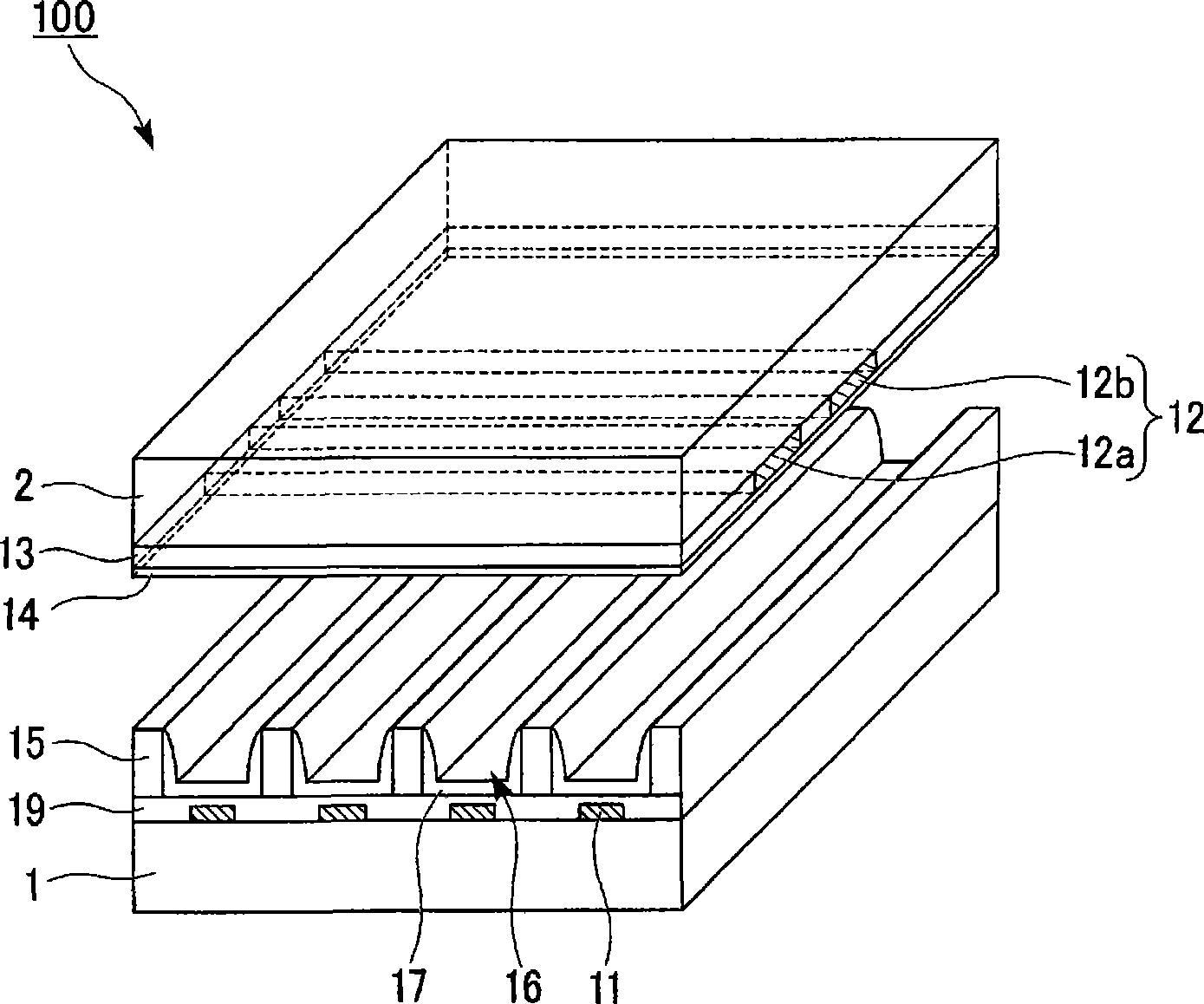
[0055] figure 1 It is an exploded perspective view of a three-electrode AC type plasma display panel. This plasma display panel (hereinafter referred to as "PDP") 100 includes a rear substrate 1 and a front substrate 2 arranged to face each other, and a plurality of discharge cells 16 formed between the substrates 1 and 2 .

[0056]Stripe address electrodes 11 are formed at predetermined intervals on the inner surface of rear substrate 1 . To cover the address electrodes 11, a diele...


PUM


Abstract

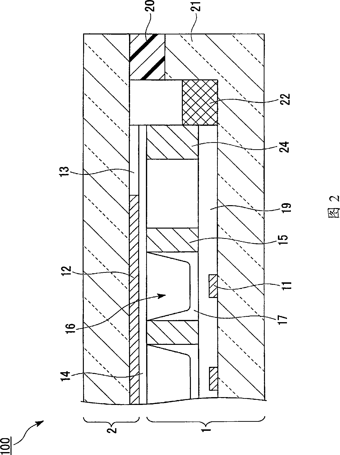
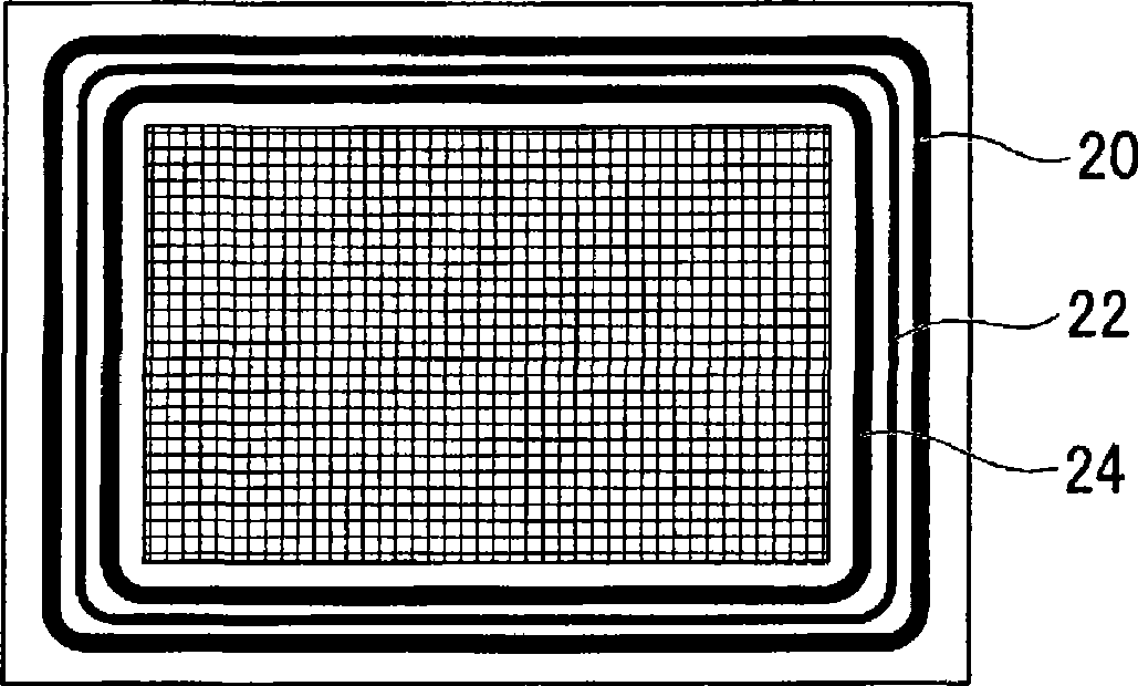
This invention provides a sealing panel (100) that can suppress a rise in discharge voltage. The sealing panel (100) comprises a resin material-containing sealing material (20) disposed on the whole periphery in a part between a pair of substrates (1,2). A getter (22), which adsorbs an impurity gas released from the sealing material (20) and an impurity gas passed through the sealing material (20), is formed continuously or intermittently along the inner periphery of the sealing material (20). Further, an ultraviolet shielding wall (24) for preventing ultraviolet light generated within the sealing panel (100) from being incident to the sealing material (20) is formed continuously along the inner periphery of the sealing material (20).

Description

technical field [0001] The invention relates to a method for manufacturing a sealing panel and a plasma display panel. [0002] this application claims priority based on Japanese Patent Application No. 2006-107547 for which it applied to Japan on April 10, 2006, and uses the content here. Background technique [0003] The plasma display panel includes a front substrate on which sustain electrodes and scan electrodes are formed, and a rear substrate on which address electrodes and phosphors are formed. The two substrates are fixed by a sealing material arranged at the peripheral portion, and a discharge gas is sealed between the two substrates. [0004] When a voltage is applied between the electrodes, the discharge gas forms plasma and emits ultraviolet rays. The ultraviolet rays enter the phosphor to excite the phosphor to emit visible light. [0005] Conventionally, low-melting-point glass has been used as a sealing material for both substrates, but a technique using a ...

Claims


Application Information

Patent Timeline
Patent Type & Authority Applications(China)
IPC IPC(8): H01J5/20H01J7/18H01J9/02H01J11/02H01J11/24H01J11/36H01J11/46H01J11/48H01J11/52
CPCH01J11/52H01J9/261H01J11/12H01J9/39H01J11/48
Inventor 仓内利春饭岛荣一
Owner ULVAC INC
Learn More