
Method and system for detecting ultra-broadband optical spectrum of ultrahigh-resolution spectrum field OCT

An ultra-high resolution, spectral detection technology, applied in the field of optical coherence tomography, which can solve the problems of reduced spectral resolution spectral domain OCT imaging depth, different focusing positions of different colors, and reduced system axial resolution, etc. Effects of spectral crosstalk, improved resolution, and improved multiplexing capabilities

Inactive Publication Date: 2009-05-13
ZHEJIANG UNIV
View PDF5 Cites 21 Cited by
  • Summary
  • Abstract
  • Description
  • Claims
  • Application Information

AI Technical Summary

Problems solved by technology

Since the increase in the number of linear CCD pixels means an increase in the field of view, unless a more complex optical imaging system is designed, serious field curvature will inevitably appear on the image surface (CCD photosensitive surface), and due to the spectral range If it is too wide, the dispersion phenomenon is serious, resulting in different focusing positions of different colors of light, which makes the spectrometer unable to completely separate the various colors of light and introduces cross-talk (cross-talk), the detection signal-to-noise ratio decreases and the axial resolution of the system decreases, ultimately reducing the imaging quality
Reducing the spectral resolution of the spectrometer means reducing the imaging depth of spectral domain OCT

Method used


Image

  • Method and system for detecting ultra-broadband optical spectrum of ultrahigh-resolution spectrum field OCT
  • Method and system for detecting ultra-broadband optical spectrum of ultrahigh-resolution spectrum field OCT
  • Method and system for detecting ultra-broadband optical spectrum of ultrahigh-resolution spectrum field OCT

Examples


Embodiment Construction

[0026] Below in conjunction with accompanying drawing and embodiment the present invention will be further described:

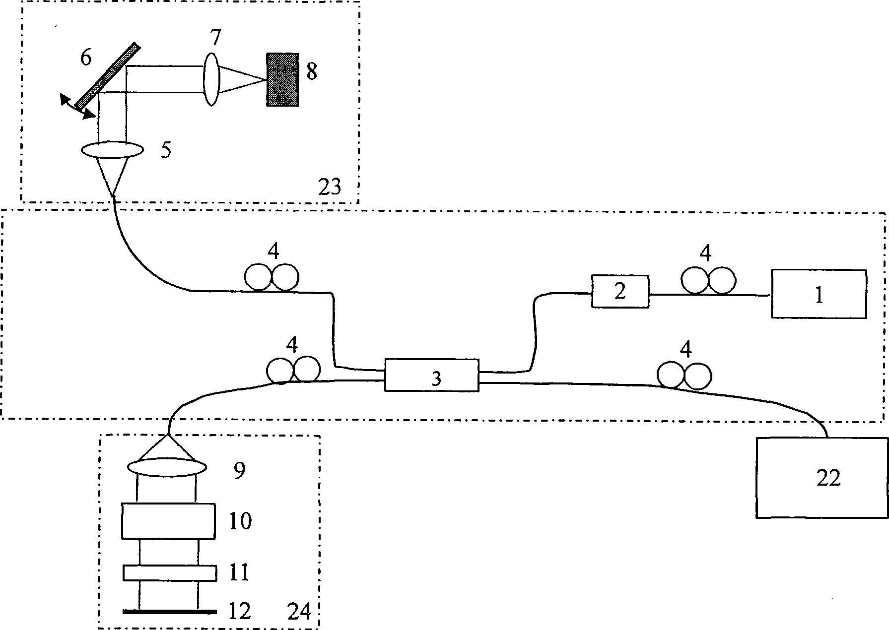
[0027] like figure 1 As shown, in the present invention, the low-coherence light from the broadband light source 1 enters the broadband fiber coupler 3 through the first polarization controller 4 and the optical isolator 2, and enters the scanning probe 23 through the second polarization controller 4 all the way after being split. , the other path enters the reference arm 24 through the third polarization controller 4, and after the returned light interferes in the broadband fiber coupler 3, passes through the fourth polarization controller 4 and enters the detection arm 22 to decompose the interference signal into different spectra, and finally These spectral signals are transmitted to the computer, where they are processed and the image is reconstructed by inverse Fourier transform.

[0028] The scanning probe 23: consists of a collimating lens 5, a scanni...


PUM


Abstract

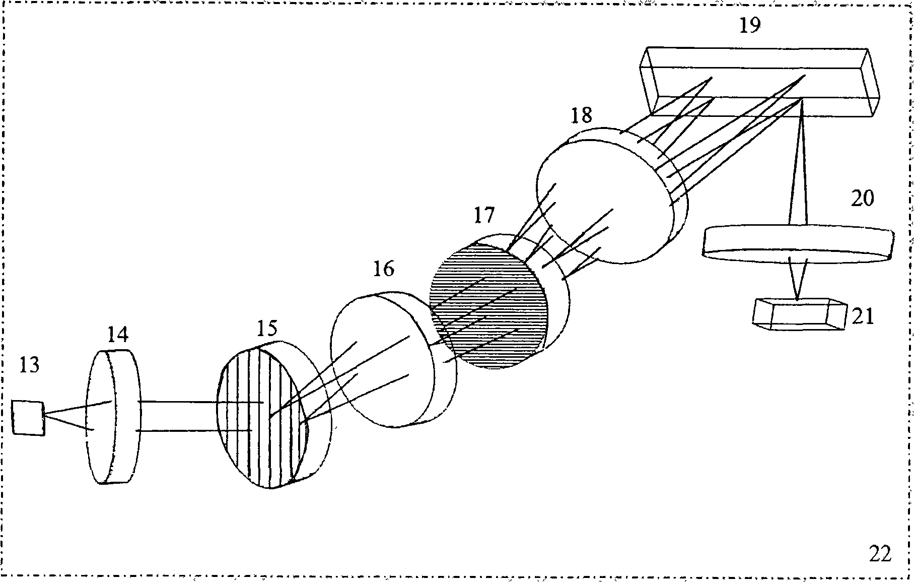
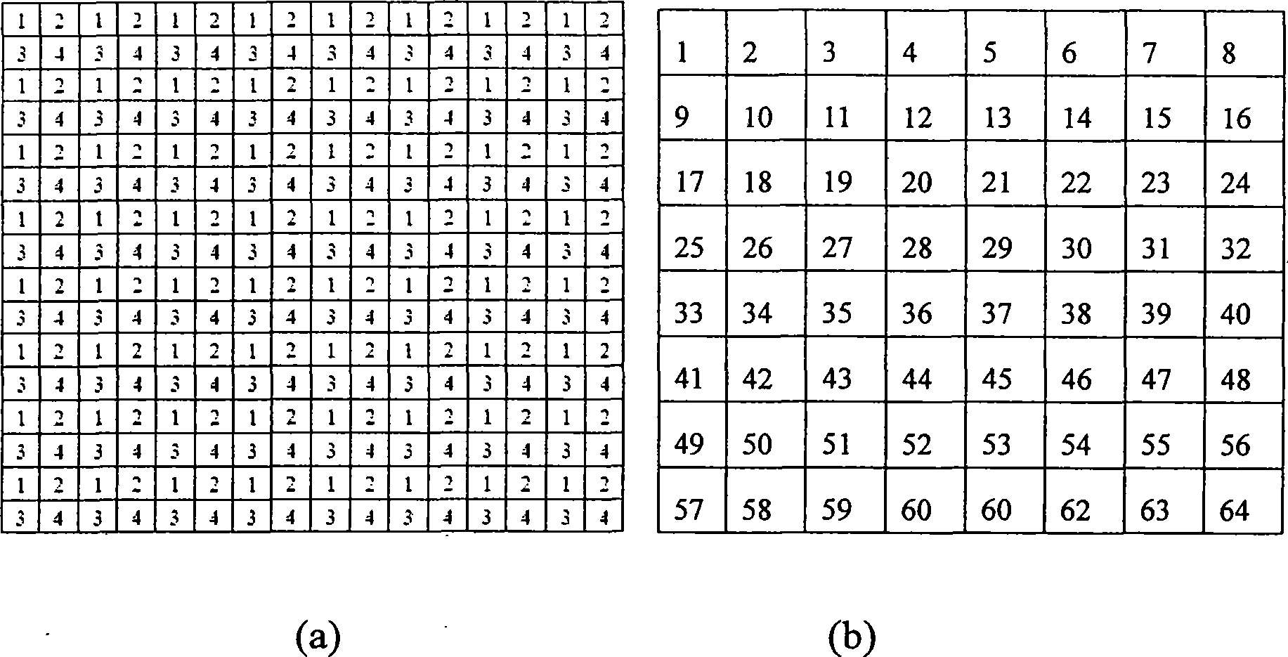
The invention discloses an ultra-wideband spectrum detection method of an ultrahigh resolution spectral-domain OCT and a system. Low-coherence light emitted from a broadband light source enters a broadband optical fibre coupler through a photoisolator, and respectively enters a scanning probe and a reference arm after light splitting; returned light is processed through interference in the broadband optical fibre coupler; and interference signals are transformed into different spectrums in a detection arm, the spectrums are processed after being transmitted into a computer, and an image is reconstructed through inverse Fourier transform. A double grating is introduced into the detection arm to generate orthogonal chromatic dispersion, and a DMD and an area array CCD are utilized to realize the fast parallel detection of the ultra-wideband spectrum at the same time. A double grating system can reduce the field coverage of a spectral imaging system, and solve the problems such as field curvature, spectrum interference and the like during imaging of large field coverage spectrum; and the DMD increases the range of the CCD spectrum measurement with finite scales and finite pixel numbers and the resolution response of the spectrum measurement, and realizes the super resolution detection of the ultra-wideband spectrum at the same time, thereby realizing high Signal-to-Noise and ultrahigh resolution spectral-domain OCT imaging.

Description

technical field [0001] The invention relates to optical coherence tomography technology, in particular to an ultra-broadband spectral detection method and system of ultra-high resolution spectral domain OCT. Background technique [0002] Optical coherence tomography (OCT) is an emerging optical imaging technology that can realize non-contact, non-invasive, high-resolution imaging of the tissue structure and physiological functions inside the living body, and can be used for early detection of diseases. And in the field of body biopsy has a wide range of applications. [0003] The current spectral domain OCT system uses a high-speed linear array CCD to collect the spectral components of the interference signal in parallel, and can obtain the depth information of the sample without axial scanning. It has the characteristics of fast and high sensitivity. The core of the system is the fast grating spectrometer of the detection arm. . In the OCT system, the axial resolution of ...

Claims


Application Information

Patent Timeline
IPC IPC(8): A61B5/00G01N21/45
Inventor 丁志华王凯王川孟婕吴彤陈明惠徐磊
Owner ZHEJIANG UNIV
Learn More