
Ultra-redundancy all-directional movable operating arm

A technology of all-round movement and mobile operation, applied in the field of manipulators, can solve the problems of limited working space and working range, lack of ability to walk in all directions, difficulty in adapting to complex working environments, etc. The effect of disassembly and assembly and resource saving

Active Publication Date: 2010-07-21
HARBIN INST OF TECH
View PDF0 Cites 2 Cited by
  • Summary
  • Abstract
  • Description
  • Claims
  • Application Information

AI Technical Summary

Problems solved by technology

[0004] In order to solve the problem that the existing operating robots have poor operational flexibility and lack the ability to walk in all directions, resulting in the limitation of their working space and operating range and making it difficult to adapt to complex working environments, the present invention further provides a super-redundant full robot Azimuth mobile manipulator

Method used


Image

  • Ultra-redundancy all-directional movable operating arm
  • Ultra-redundancy all-directional movable operating arm
  • Ultra-redundancy all-directional movable operating arm

Examples


specific Embodiment approach 1

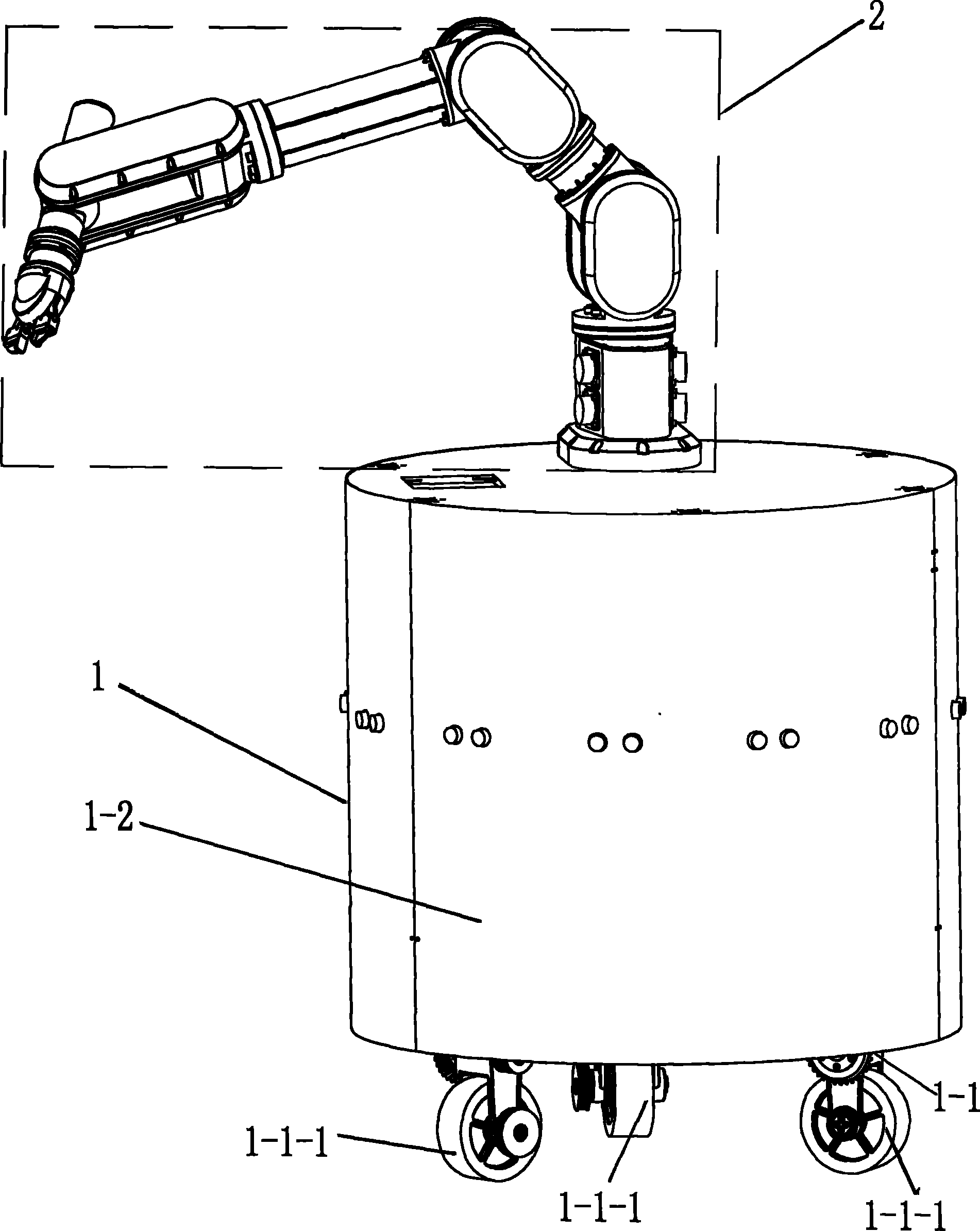
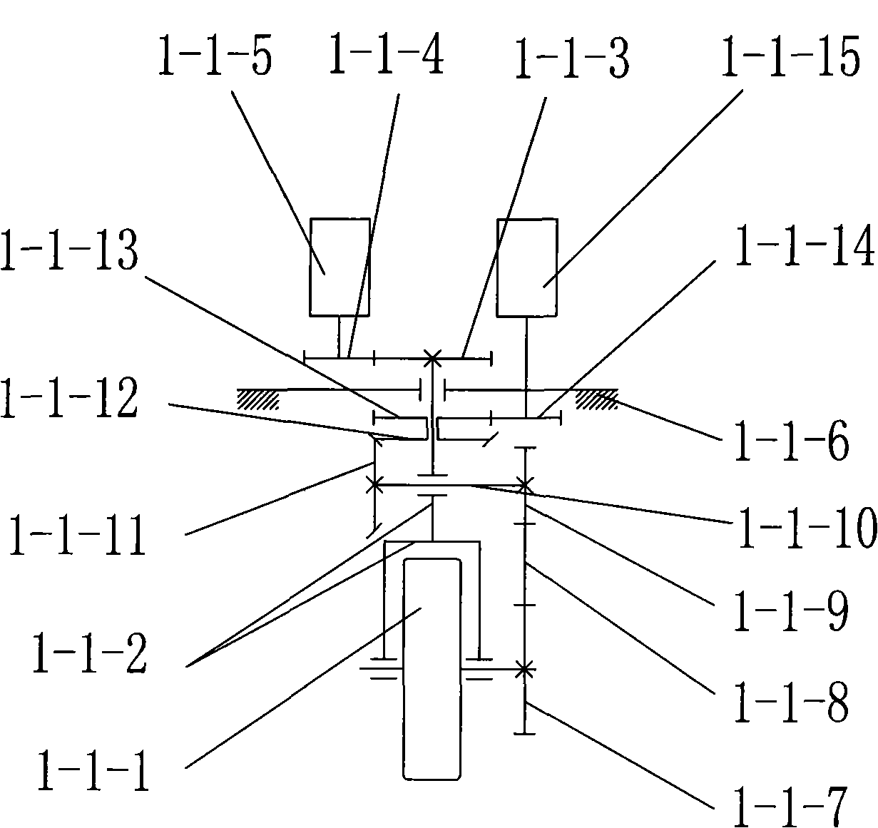
[0008] Specific implementation mode one: as Figure 1~3 As shown, the super-redundant omnidirectional mobile operating arm described in this embodiment is composed of an operating arm main body 2 and an omnidirectional mobile trolley 1. The operating arm main body 2 is installed on the upper end surface of the omnidirectional mobile trolley 1. The omnidirectional Mobile trolley 1 is made up of at least three wheel modules 1-1 and outer casing 1-2, and each wheel module 1-1 is all made up of wheel body 1-1-1, frame 1-1-6, wheel steering device and wheel The wheel steering device is composed of a steering bracket 1-1-2, a first steering spur gear 1-1-3, a second steering spur gear 1-1-4 and a steering motor 1-1-5. The rolling device consists of the first synchronous pulley 1-1-7, the synchronous belt 1-1-8, the second synchronous pulley 1-1-9, the rotating shaft 1-1-10, the first bevel gear 1-1-11, The second bevel gear 1-1-12, the first rolling spur gear 1-1-13, the second rol...

specific Embodiment approach 2

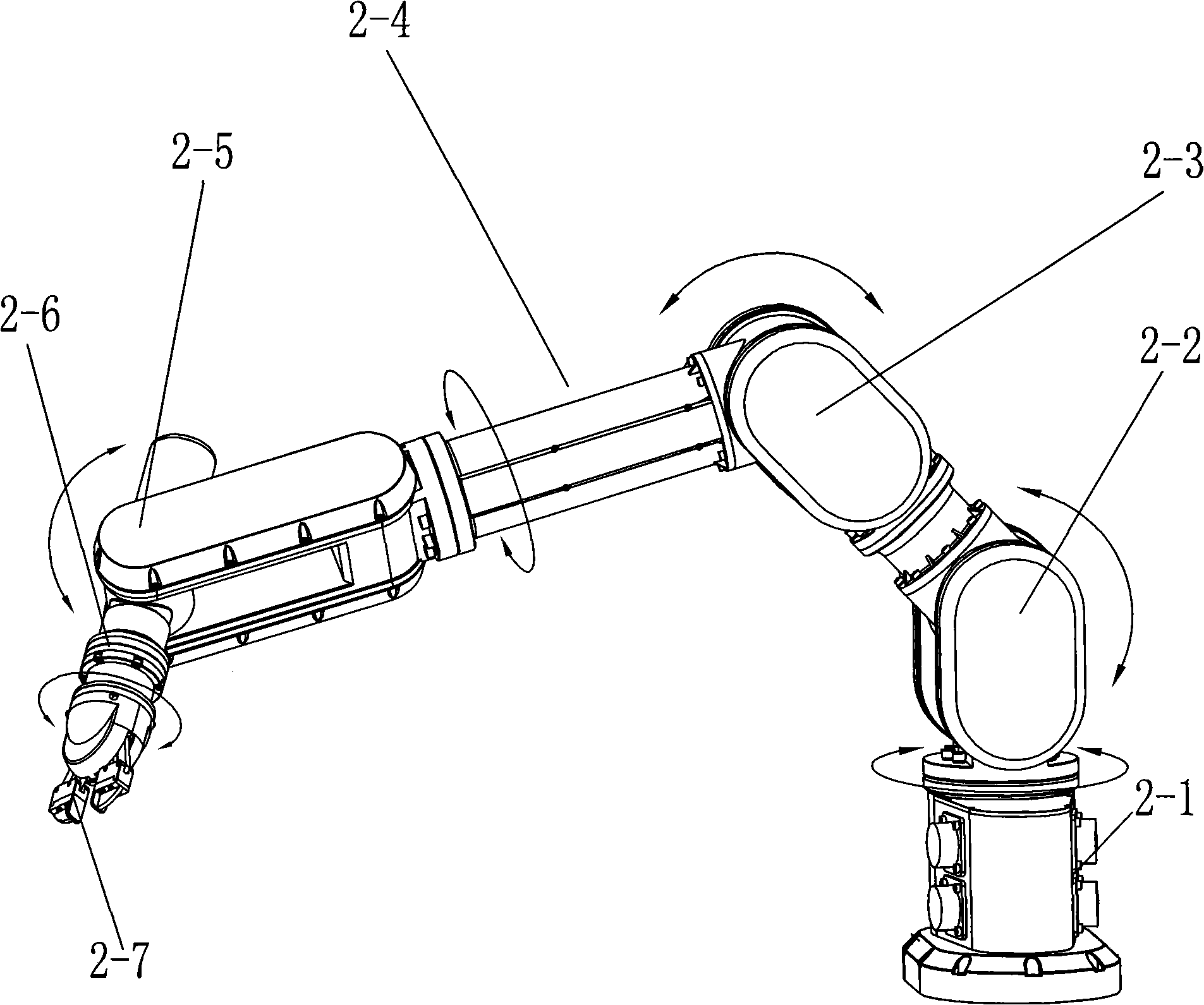
[0010] Specific implementation mode two: as Figure 1~4 As shown, the main body 2 of the operating arm in this embodiment includes a waist joint module 2-1, a shoulder joint module 2-2, an elbow joint module 2-3, a wrist joint first module 2-4, a wrist joint second module 2-5 and Wrist joint three modules 2-6 six joint modules, the waist joint module 2-1, shoulder joint module 2-2, elbow joint module 2-3, wrist joint one module 2-4, wrist joint two module 2-5 Connect with the three wrist modules 2-6 in sequence. The main body 2 of the operating arm described in this embodiment is an operating arm with six degrees of freedom, and the operating arm with six degrees of freedom is installed on the omni-directional mobile trolley 1 with three degrees of freedom to realize a super-redundant full Move the operating arm in azimuth, so that the operating arm has the mobility of the mobile platform and the operability of the operating arm at the same time, with almost infinite work spa...

specific Embodiment approach 3

[0012] Specific implementation mode three: as Figure 1~3 As shown, the main body 2 of the operating arm in this embodiment further includes a jaw 2-7, and the jaw 2-7 is connected to the end of the third module 2-6 of the wrist joint. Other components and connections are the same as those in the second embodiment.


PUM


Abstract

A super-redundant all-position mobile manipulator arm relates to manipulator arms, and solves the problem that the operational flexibility of the prior operating robot is poor and the prior operating robot is not capable of all-position walking, so that the working space and the working range thereof are limited to prevent the operating robot from adapting to complex working conditions. The manipulator arm is characterized in that a first steering spur gear is meshed with a second steering spur gear which is connected with the output shaft of a steering motor; a first synchronous belt wheel is connected with a second synchronous belt wheel through a synchronous belt; the second synchronous belt wheel is connected with a first bevel gear through a rotating shaft which is mounted on a steering bracket; the first bevel gear is meshed with a second bevel gear; both the second bevel gear and a first rolling spur gear are mounted on the steering bracket; the first rolling spur gear is meshed with a second rolling spur gear; and the second rolling spur gear is connected with the output shaft of a rolling motor. The manipulator arm has the advantages of higher manipulability, strong task compatibility, large working space and good flexibility, thereby performing the all-position moving function.

Description

technical field [0001] The invention relates to an operating arm. Background technique [0002] With the increasing application of robots in the field of human life, higher requirements are placed on the performance of robots in terms of operational flexibility, operating range, and adaptability to complex operations. [0003] At present, the traditional operating robots are all mechanical arms with fixed bases, and use their operating performance to complete some operations in a fixed area (accessible space for claws) such as assembly and welding. Although it is relatively simple to control, its limitations are also very obvious. For example, when it is necessary to maintain the entire production line or multiple pieces of equipment, since the fixed base restricts the gripper to operate in a fixed area, it can only meet the operation requirements by arranging multiple operating arms, which not only increases the cost, but also causes A waste of resources. In addition, wi...

Claims


Application Information

Patent Timeline
Patent Type & Authority Patents(China)
IPC IPC(8): B25J5/00B25J18/00B25J17/00
Inventor 赵杰闫继宏樊继壮唐术锋刘刚峰
Owner HARBIN INST OF TECH
Learn More