High-speed phase discriminator

A phase detector, high-speed technology, applied in the direction of pulse technology, automatic power control, pulse generation, etc., can solve the problems of phase detector minimum phase difference, insufficient working speed, and dead zone problems, so as to solve the problem of dead zone Problems, high working speed, and the effect of improving the accuracy of phase identification

Inactive Publication Date: 2011-08-24
EAST CHINA NORMAL UNIV
View PDF0 Cites 2 Cited by
  • Summary
  • Abstract
  • Description
  • Claims
  • Application Information

AI Technical Summary

Problems solved by technology

This kind of phase detector has a large capture range, fast locking speed, and relatively simple circuit, but it also has many shortcomings, such as the dead zone problem, which refers to the minimum phase difference that the phase detector can identify; the working speed is not fast enough , only about 100MHz, unable to meet the requirements of current products

Method used


Image

  • High-speed phase discriminator
  • High-speed phase discriminator
  • High-speed phase discriminator

Examples


Embodiment

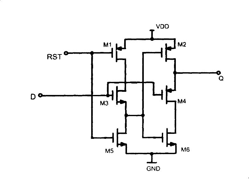
[0018] The width-to-length ratios of the first MOS transistor M1, the second MOS transistor M2, and the fourth MOS transistor M4 are all 2 μm / 0.18 μm, and the width-to-length ratios of the third MOS transistor M3, the fifth MOS transistor M5, and the sixth MOS transistor M6 are all 2 μm / 0.18 μm. is 1μm / 0.18μm;

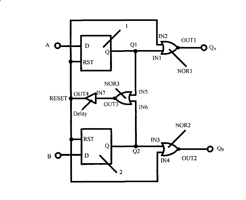
[0019] The delay unit Delay is formed by cascading two stages of NOT gates. The width-to-length ratio of the PMOS tube in the NOT gate is 10 μm / 0.6 μm, and the width-to-length ratio of the NMOS tube is 5 μm / 0.6 μm.

[0020] The supply voltage is 1.8V;

[0021] The working speed is 900MHz.

[0022] Combine below Figure 4 The working principle of the high-speed phase detector of this embodiment will be described in detail. exist Figure 4 Among them, the MOS transistor used by the second D flip-flop 2 uses the first 'MOS transistor M1', the second 'MOS transistor M2', the third 'MOS transistor M3', and the fourth 'MOS transistor M3' corresponding to the first D flip...


PUM


Abstract

The invention relates to a high-speed phase detector, in particular to a high-speed phase detector based on the single-phase-clock dynamic CMOS technology, belonging to the technical field of signal processing and the circuit thereof. Based on the traditional phase detector, a time delay module is added to a feedback loop, so that no dead zone exists when the phase detector is in operation; and ahigh speed D trigger is used for replacing the traditional low speed D trigger, thereby causing the working speed of the phase detector to reach 900 MHz. The phase detector has the advantages of highworking speed, easy manufacture, and no dead zone during the operation, and is especially suitable for precisely differentiating the phase difference of two input signals in a delay-locked loop.

Description

technical field [0001] The invention relates to a high-speed phase detector, to be precise, relates to a high-speed phase detector based on single-phase clock dynamic CMOS technology, and belongs to the technical field of signal processing and its circuit. Background technique [0002] With the rapid development of integrated circuit technology, the operating frequency of the microprocessor is increasing year by year. At present, Intel has launched a microprocessor chip with a main frequency exceeding 3GHz. The main frequency of general-purpose microprocessor chips is generally above 100 MHz. Due to the limitations of PCB technology, it is difficult for the motherboard to provide a clock signal above 200MHz for the chip. Therefore, a stable high-frequency clock generation circuit is required inside the chip. With the improvement of people's requirements for low power consumption, short lock-up time and high speed, the traditional high-frequency clock generation circuit can...

Claims


Application Information

Patent Timeline
Patent Type & Authority Patents(China)
IPC IPC(8): H03L7/085H03K3/012H03K3/356
Inventor 马和良雷奥赖宗声周灏赖琳晖陈磊杨华刘琳陈子晏欧阳炜霞
Owner EAST CHINA NORMAL UNIV
Why Eureka
Try Eureka