Detonation velocity photoelectric test method and apparatus of detonating cord

A photoelectric testing and detonating cord technology, applied in the field of mechatronics, can solve the problems of large volume, complex structure, low reliability, etc., and achieve the effects of strong anti-interference ability, broad application prospects and high testing accuracy.

Inactive Publication Date: 2009-05-20
ZHONGBEI UNIV
View PDF1 Cites 25 Cited by
  • Summary
  • Abstract
  • Description
  • Claims
  • Application Information

AI Technical Summary

Problems solved by technology

[0005] Chinese Patent Publication No.: CN2123753U discloses a timing method explosive detonation velocity detector, which proposes the optical measurement method with optical fiber, but the signal processing circuit has four parallel circuits, and the components adopt separate devices, which have low reliability and large volume
Judging from the published literature, there are reports on the probe method for detonation velocity measurement at home and abroad, and optical fiber is also used for detonation velocity measurement research, but their structures are relatively complicated and are only suitable for application in laboratories.
For example, the article "Application of Optical Fiber in Burning Velocity and Detonation Velocity Test" published in "Pyrotechnics" in 2000 researched the burning velocity of optical fiber used in pyrotechnics and the detonation velocity of

Method used


Image

  • Detonation velocity photoelectric test method and apparatus of detonating cord
  • Detonation velocity photoelectric test method and apparatus of detonating cord
  • Detonation velocity photoelectric test method and apparatus of detonating cord

Examples


Example Embodiment

[0015] The present invention will be further described below in conjunction with the accompanying drawings.

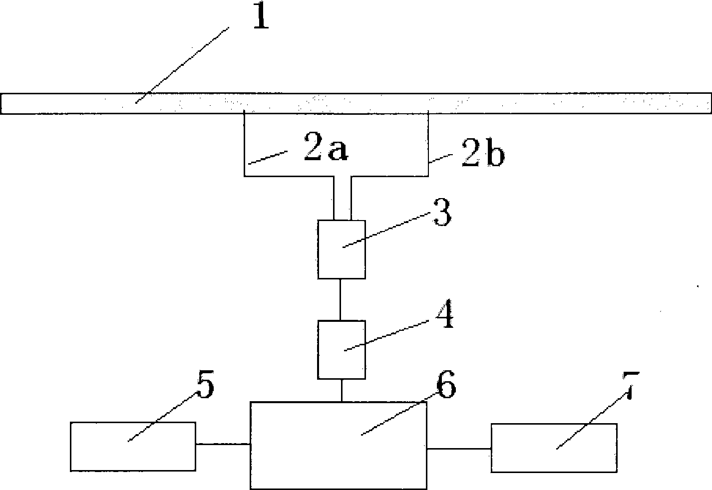
[0016] like figure 1 Shown, detonating cord detonation velocity photoelectric testing device of the present invention comprises two (N) multimode fiber probes (N >= 2) that multimode fiber is made with multimode fiber, and the typical example of this explanation is with two multimode fiber probes 2a, 2b as an example), multi-fiber coupling connector 3, PIN integrated photodetector or solid-state photomultiplier tube detector 4, power supply 5, FPGA high-speed data acquisition module 6 and liquid crystal display 7. The multimode fiber probes 2a, 2b are inserted on the detonating cord 1 at a certain distance, and the two (N) multimode fiber probes are simultaneously connected to a multi-fiber coupling connector, and the multi-fiber coupling connector Connect to the input end of the PIN integrated photodetector or solid-state photomultiplier tube detector through a pigta...


PUM


Abstract

The invention relates to a photoelectric testing method for the detonating speed of a detonating fuse and a device thereof. The device is characterized in that the device at least comprises two multimode fibre probes inserted into the detonating fuse in certain distance, a fibre coupling connector, a PIN integrated photoelectric detector, a power supply, an FPGA high-speed data acquisition module and a liquid crystal display screen; the PIN integrated photoelectric detector is used to carry out time sharing processing on the temporal fore-and-aft relation of optical signals acquired by the probes in time; optical signals of a plurality of probes are converted into pulse electric signals and are transported to the FPGA high-speed data acquisition module; the input pulse electric signals are subjected to sampling, calculation processing, control and caching; the distance of each two probes of the plurality of the probes and the measured time are subjected to calculation processing to seek an average speed; the detonating speed and relevant data of the detonating fuse are transmitted to the liquid crystal display screen and are displayed; and the photoelectric testing method has the advantages of high testing precision, strong antijamming capacity, small volume, simple operation and the like.

Description

technical field [0001] The invention belongs to the field of machinery and electronics, and mainly relates to a detonating cord detonation velocity testing technology, in particular to a detonating cord detonation velocity photoelectric testing method and device based on a multimode optical fiber probe. Background technique [0002] The detonating cord is made of explosives as the drug core and coated with a moisture-proof agent on the surface. It is also called the detonating wire. It is an industrial explosive product that transmits detonation waves at a certain detonation speed. Detonation work. When the explosive core at the end of the detonating cord is stimulated by a certain intensity of explosion impact energy, it is detonated, and the detonation propagates along the charge core at a certain speed. When it reaches the end, the detonation is completed and a shock wave of a certain intensity is output. Used to detonate other explosives. The speed at which the detonat...

Claims


Application Information

Patent Timeline
IPC IPC(8): G01P3/64F42B35/00
Inventor 王高孙巍赵辉王小燕李仰军周汉昌
Owner ZHONGBEI UNIV
Why Eureka
Try Eureka