
Optical fiber laser dynamic focusing vibration mirror scanning type spot welding system and welding method thereof

A dynamic focusing and galvanometer scanning technology, applied in laser welding equipment, welding equipment, optics, etc., can solve the problems of uncontrolled welding points, the charging and discharging speed of the laser power supply cannot meet the requirements, and the scanning speed of the galvanometer is fast.

Inactive Publication Date: 2009-05-27
广州瑞通千里激光设备有限公司
View PDF0 Cites 31 Cited by
  • Summary
  • Abstract
  • Description
  • Claims
  • Application Information

AI Technical Summary

Problems solved by technology

The scanning speed of the galvanometer is too fast, the charging and discharging speed of the laser power supply cannot meet the requirements, and the position of the welding point does not match the setting in the PC control software, resulting in defects such as uncontrolled welding points

Method used


Image

  • Optical fiber laser dynamic focusing vibration mirror scanning type spot welding system and welding method thereof
  • Optical fiber laser dynamic focusing vibration mirror scanning type spot welding system and welding method thereof

Examples


Embodiment

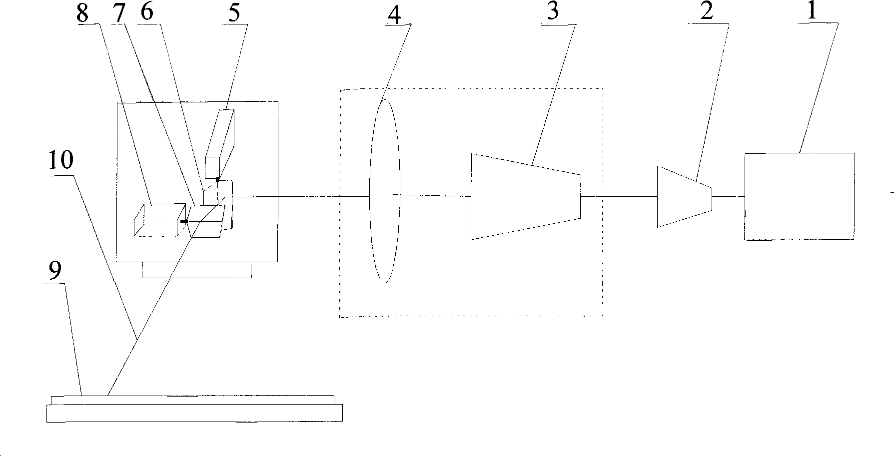
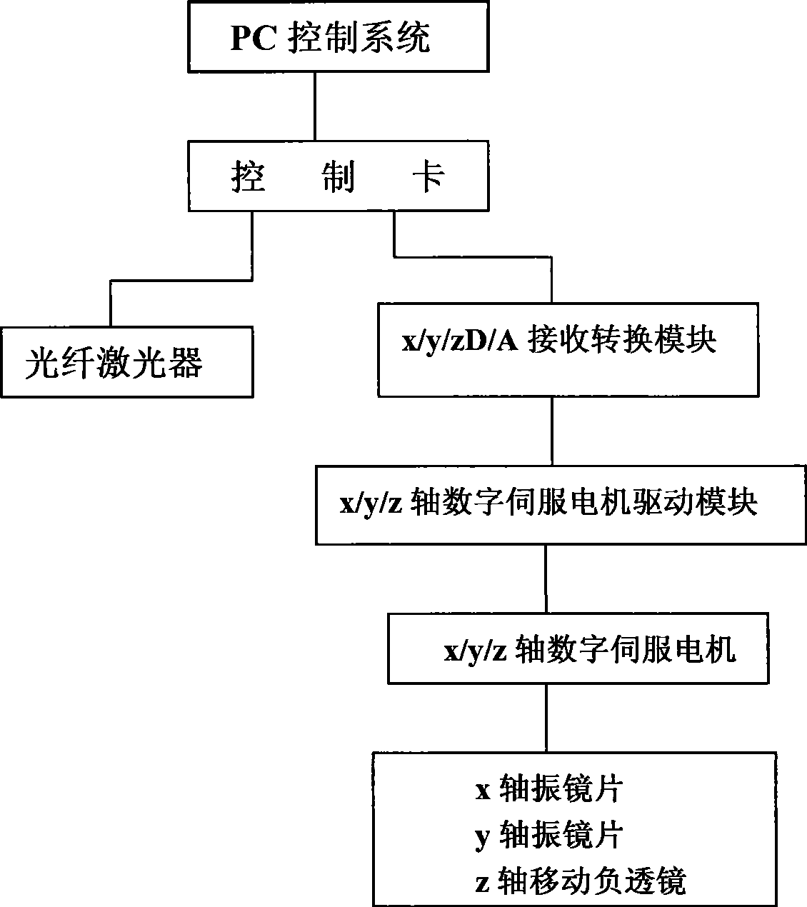
[0022] Such as figure 1 , figure 2 As shown, the fiber laser dynamic focusing vibrating mirror scanning spot welding system of the present invention includes a PC control system and a fiber laser 1, a beam expander 2, a dynamic focusing unit, an X-axis vibrating mirror 5, and a Y-axis vibrating mirror 7. The X-axis vibrating mirror 5 is mounted on the rotating shaft of the X-axis digital servo motor 6, the Y-axis vibrating mirror 7 is mounted on the rotating shaft of the Y-axis digital servo motor 8, and the dynamic focusing unit is composed of a moving negative lens 3 Composed of focusing lens 4, the moving negative lens 3 is installed on the rotating shaft of the Z-axis digital servo motor (not shown in the figure), and the PC control system is connected with the X-axis digital servo motor, Y-axis digital servo motor, Z Axis digital servo motor signal connection.

[0023] The output power of the fiber laser 1 is 100-150 W, and the wavelength is 1060-1090 nm, and the focus...


PUM

PropertyMeasurementUnit
poweraaaaaaaaaa
wavelengthaaaaaaaaaa

Abstract

The invention discloses an oscillating-mirror scanning spot welding system which focuses optical-fibre laser dynamically. The system comprises a PC control system and a fibre laser, a beam expanding lens, a dynamic focusing unit, an X-axis vibration lens and a Y-axis vibration lens which are connected in sequence along a light path. The X-axis vibration lens is arranged on a rotating shaft of an X-axis servo motor; the Y-axis vibration lens is arranged on a rotating shaft of a Y-axis servo motor; the dynamic focusing unit consists of a moving negative lens and a focusing lens; the moving negative lens is arranged on a rotating shaft of a Z-axis servo motor; and a stepping motor is controlled by a PC or hand control, so as to realize long-distance travel of the moving negative lens and the Z-axis servo motor along the transferring direction of the light beam, thereby obtaining different working distances (focuses); therefore, the corresponding scanning range changes between 200 millimetres and 1450 millimetres and the spot diameter is between 30 microns and 200 microns.

Description

technical field [0001] The invention relates to laser welding technology, in particular to an optical fiber laser dynamic focusing vibrating mirror scanning spot welding system and a welding method thereof. Background technique [0002] In many industrial laser welding applications, tens to hundreds of points need to be welded on a workpiece. Compared to laser beam positioning and workpiece loading time, welding time is relatively short, and typical welding time accounts for about 20% to 50% of the entire welding process. Scanner welding, also known as remote welding, is a dynamic welding process using a scanning mirror group. This process has the main advantages of long focal length and highly flexible laser beam offset. The laser beam Positioning on the working surface is achieved by the deflection of two mirrors, one or two galvanometers within the scanning lens to switch the laser beam quickly between the weld seams in almost zero time. The greater the number of solder...

Claims


Application Information

Patent Timeline
Patent Type & Authority Applications(China)
IPC IPC(8): B23K26/04G02B26/10B23K26/046
Inventor 王红卫杨永强王迪包渠平
Owner 广州瑞通千里激光设备有限公司
Learn More