
Method for preparing transparent low resistance/high resistance composite membrane used for thin-film solar cell

A technology of solar cells and composite films, which is applied in the manufacture of circuits, electrical components, and final products, can solve problems such as complex processes, and achieve the effects of reducing production costs, shortening production cycles, and reducing production links

Inactive Publication Date: 2009-06-03
上海太阳能电池研究与发展中心
View PDF2 Cites 19 Cited by
  • Summary
  • Abstract
  • Description
  • Claims
  • Application Information

AI Technical Summary

Problems solved by technology

Although these processes omit the steps of preparing high-resistance films, but add high-temperature oxidation or oxygen plasma bombardment processes, some auxiliary systems are still required, so the process is still relatively complicated.
In addition, the above-mentioned process realizes the low-resistance / high-resistance composite film through special treatment of the prepared low-resistance film, so it is only suitable for the battery structure of the upper layer configuration, but not applicable for the battery structure of the lower layer configuration

Method used


Image

  • Method for preparing transparent low resistance/high resistance composite membrane used for thin-film solar cell
  • Method for preparing transparent low resistance/high resistance composite membrane used for thin-film solar cell
  • Method for preparing transparent low resistance/high resistance composite membrane used for thin-film solar cell

Examples


Embodiment 1

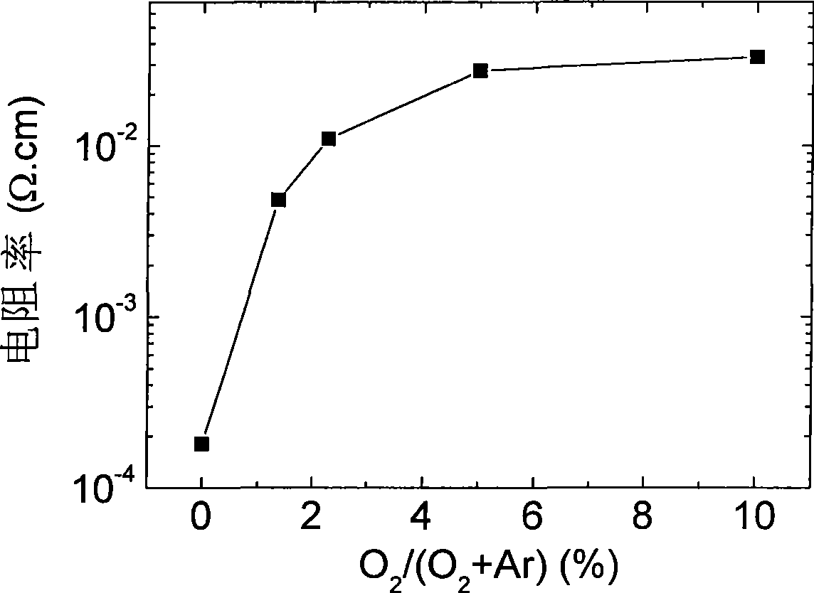
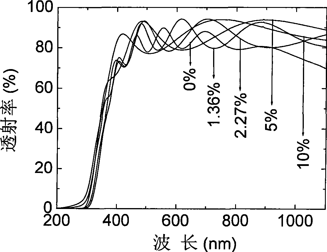
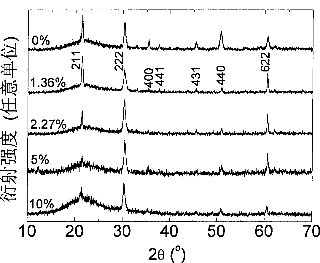
[0028] For the In of the upper layer configuration of the solar cell 2 o 3 : Sn transparent low-resistance / high-resistance composite film growth as an example, using radio frequency magnetron sputtering technology, the quartz glass substrate and In 2 o 3 : Sn sputtering target placed in the vacuum chamber of magnetron sputtering equipment, In2 o 3 : Sn target contains 10wt% SnO 2 , using mechanical pump and molecular pump to pump the vacuum chamber to 6×10 -4 Pa background vacuum.

[0029] Sputtering parameter setting: the sputtering power is 60W, the sputtering pressure is 1.6Pa, and the substrate temperature is 350°C.

[0030] Growth of transparent low-resistance / high-resistance composite films

[0031] On a transparent quartz glass substrate, a transparent low-resistance film was grown by sputtering under pure Ar sputtering gas for 55 min, and then on the transparent low-resistance film in O 2 10% Ar, O 2 Under the mixed sputtering gas, the transparent high-resistan...

Embodiment 2

[0034] Taking the growth of ZnO:Al transparent low-resistance / high-resistance composite film used for solar cells on the upper layer as an example, using radio frequency magnetron sputtering technology, the quartz glass substrate and ZnO:Al sputtering target are placed in the magnetron sputtering equipment In the vacuum chamber, the ZnO:Al target contains 2wt% Al 2 o 3 , using mechanical pump and molecular pump to pump the vacuum chamber to 6×10 -4 Pa background vacuum.

[0035] Sputtering parameter setting: the sputtering power is 80W, the sputtering pressure is 1.6Pa, and the substrate temperature is 420°C.

[0036] Growth of transparent low-resistance / high-resistance composite films

[0037] On a transparent quartz glass substrate, a transparent low-resistance film was grown by sputtering under pure Ar sputtering gas, and the sputtering time was 50 min, and then on the transparent low-resistance film, in O 2 5% Ar, O 2 Under the mixed sputtering gas, the transparent hi...


PUM

PropertyMeasurementUnit
electrical resistivityaaaaaaaaaa
thicknessaaaaaaaaaa
electrical resistivityaaaaaaaaaa

Abstract

The invention discloses a method for preparing a transparent low resistance / high resistance composite membrane used for a thin-film solar cell. By adopting the technology of magnetron sputtering and the same conductive oxide target, the method can realize the preparation of the transparent low resistance / high resistance composite membrane by controlling the oxygen content of sputtering gas. The method has the advantage that the transparent composite membrane with low resistance / high resistance or resistance gradient can be prepared in the same vacuum cavity by adopting a target under the technique condition of only changing the oxygen content in sputtering atmosphere without breaking vacuum environment. The production procedures can be reduced, the production period is shortened, and the technique and the operation are simple, so that the production cost is greatly reduced. Furthermore, the technique is simultaneously applicable to the thin-film solar cell structure with upper layer configuration and lower layer configuration.

Description

technical field [0001] The invention relates to a thin-film solar cell, in particular to a method for preparing a transparent low-resistance and high-resistance composite oxide film used for the thin-film solar cell. Background technique [0002] Due to the advantages of high efficiency and low cost, thin-film solar cells are one of the main development directions of solar cells in the future. At present, compound semiconductor solar cells have two basic structures: one is the upper layer configuration structure, that is, the upper electrode of the transparent conductive film, the n-type window layer, the p-type absorber layer and the back contact electrode are sequentially prepared on a transparent substrate (such as glass); The other is the lower layer configuration structure, that is, the back contact electrode, p-type absorption layer, n-type window layer and transparent conductive layer are sequentially prepared on the substrate (which can be a transparent glass substra...

Claims


Application Information

Patent Timeline
Patent Type & Authority Applications(China)
IPC IPC(8): H01L31/18C23C14/35C23C14/54C23C14/56C23C14/06
CPCY02P70/50
Inventor 褚君浩马建华王善力
Owner 上海太阳能电池研究与发展中心
Learn More