
Hot-melt adhesive brander

A labeling machine, hot melt adhesive technology, applied in the directions of labeling machine, labeling, labeling, etc., can solve the problems of increased space occupied, increased manufacturing cost, complex structure of the label cutting mechanism, etc. The effect of cost reduction and simple structure

Inactive Publication Date: 2009-06-17
广州市万世德智能装备科技有限公司
View PDF1 Cites 15 Cited by
  • Summary
  • Abstract
  • Description
  • Claims
  • Application Information

AI Technical Summary

Problems solved by technology

[0002] At present, a hot melt adhesive labeling machine generally includes a machine base, a bottle conveying chain, a bottle supporting carousel device and a label conveying device. The upper part is equipped with a bottle pressing mechanism. On the side of the bottle supporting carousel, there are also bottle infeed starwheels and bottle outstarwheels connected with the bottle conveying chain. The guide plate and the label conveying device include a label disc, a label tensioning conveying device, a labeling cam device, a label cutting wheel device arranged on the side of the labeling cam device, and a servo motor control system for the power of each device. There is also a hot-melt adhesive device on the side, such as Chinese patent CN200710029848.7. Since the label of this type of labeling machine uses a disc label, a set of label-cutting mechanism is required to cut the label, and the structure of the label-cutting mechanism is generally complicated. , so the manufacturing cost of the whole machine increases, and the occupied space increases

Method used


Image

  • Hot-melt adhesive brander
  • Hot-melt adhesive brander
  • Hot-melt adhesive brander

Examples


Embodiment Construction

[0024] Below in conjunction with accompanying drawing, hot melt adhesive labeling machine of the present invention is further described:

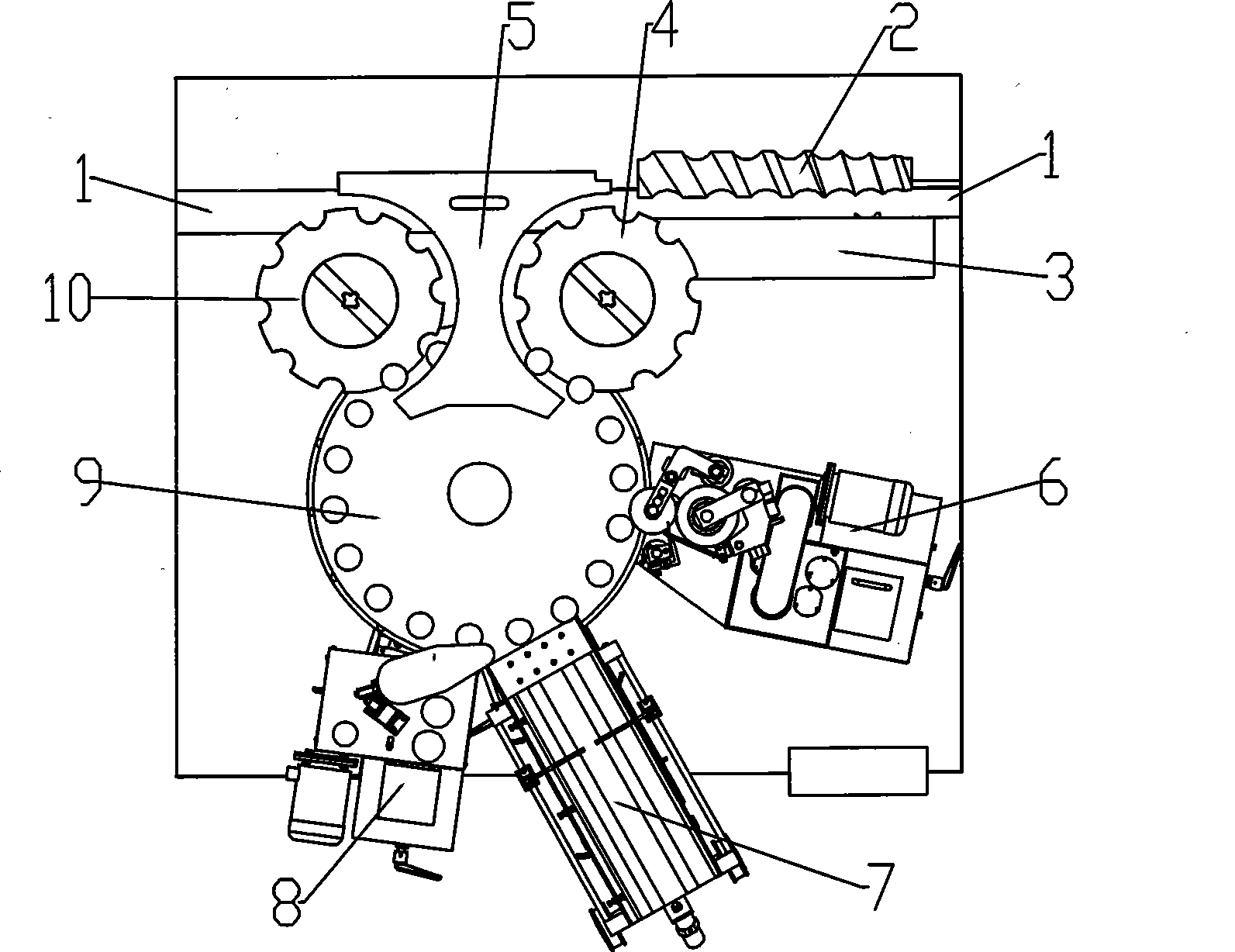
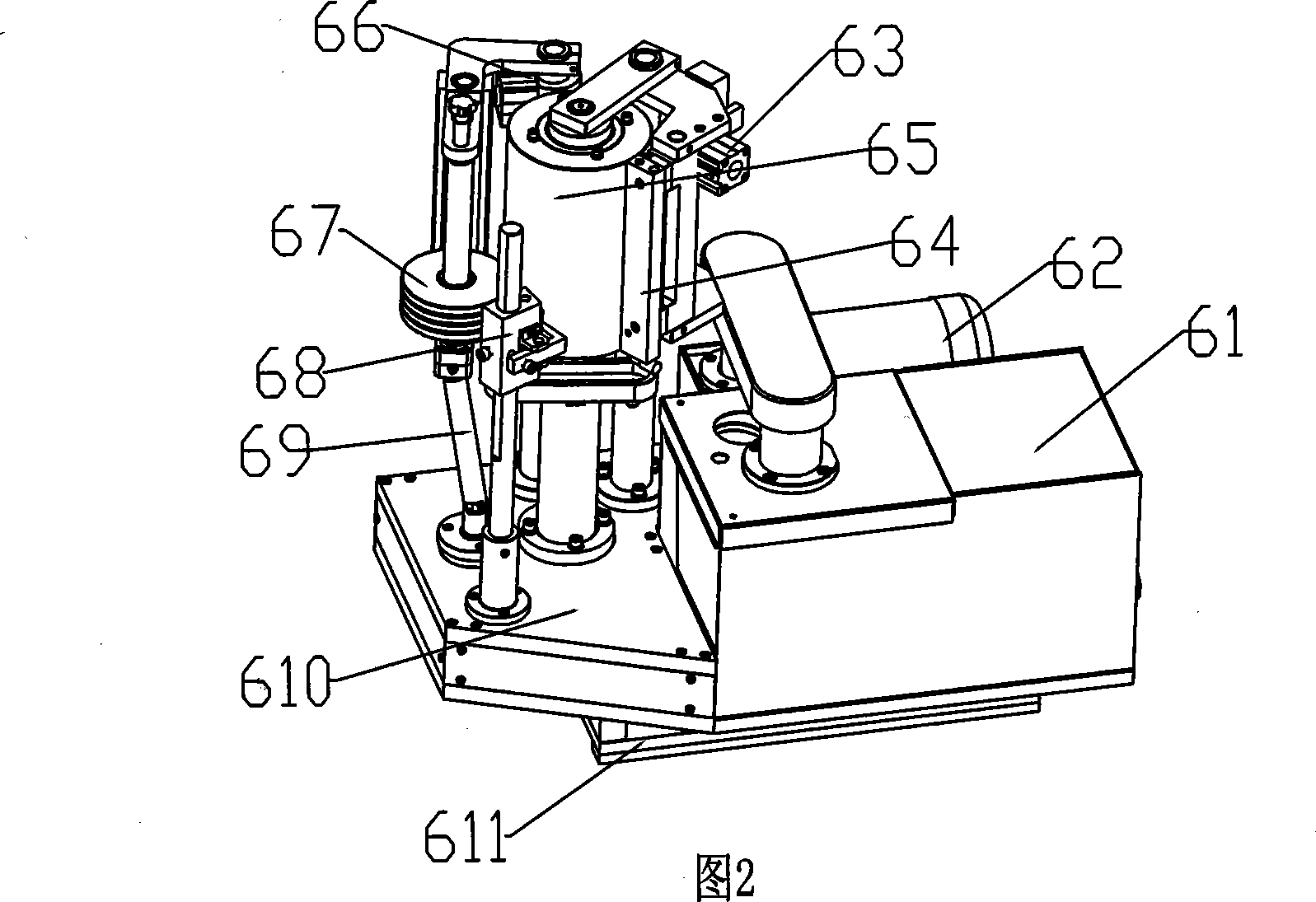
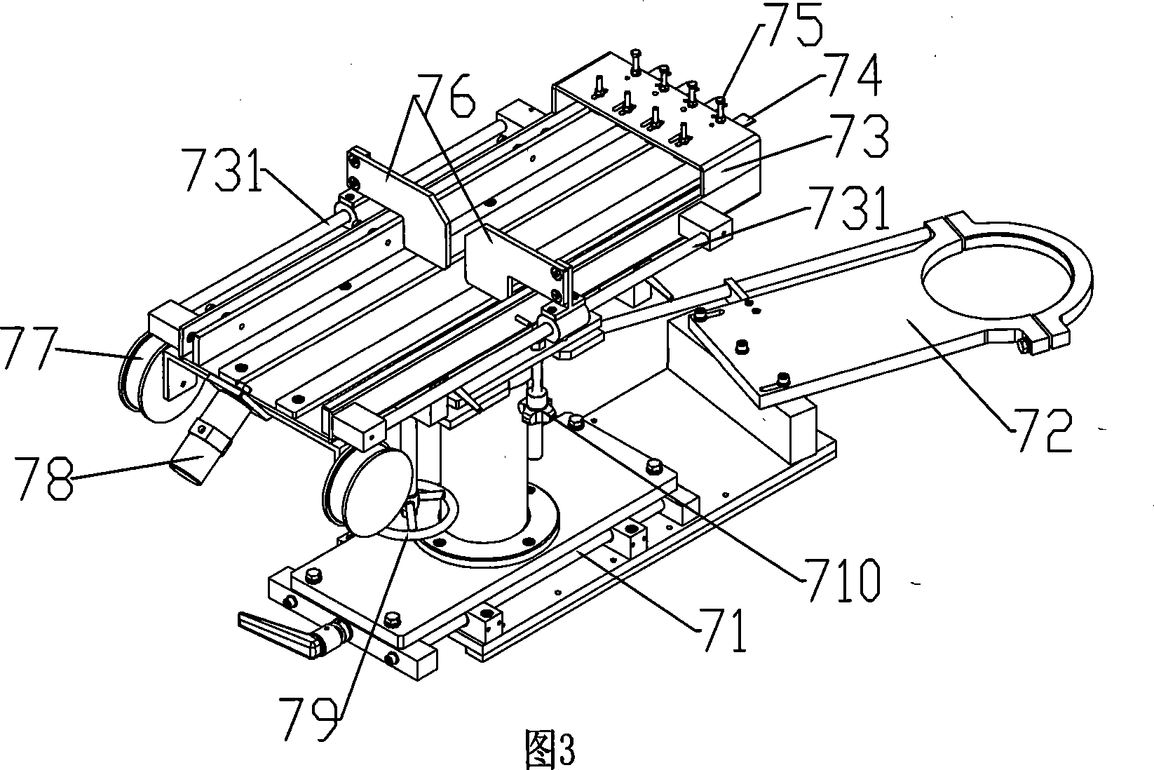
[0025] Such as figure 1 As shown, the hot melt adhesive labeling machine of the present invention includes a frame, a rotary part, a labeling part and a corresponding control part. Star wheel 4, center guide plate 5, bottle discharge star wheel 10, bottle support turntable 9, bottle support assembly 92 for accurately positioning bottles 11 on the bottle support turntable 9, bottle fixing assembly 93, bottle in and out chain path 1, namely bottle infeed chain The road and the bottle output chain road can share a chain road. The bottle supporting and fixing assembly is provided with a bottle rotating mechanism 91 that drives the bottle 11 to rotate around the axis of the bottle at a certain speed. By the side of the bottle holder turntable 9. The labeling part includes the front rubber roller device 6 which is arranged next to the side of ...


PUM


Abstract

The invention discloses a hot melt adhesive labeler, which comprises a machine frame, a gyratory part, a labeling part and a corresponding control part, wherein the gyratory part comprises a bottle input and output chain channel, a bottle feeding screw, a bottle stopping star wheel, a bottle input star wheel, a central guide plate, a bottle output star wheel, a bottle holder turnplate, a bottle holding component and a bottle positioning component which accurately position a bottle on the bottle holder turnplate; the bottle holding component is provided with a bottle rotating mechanism for driving the bottle to rotate around the axial line of the bottle according to certain rotating speed; and the central guide plate is arranged between the bottle feeding star wheel and the bottle output star wheel and the side of the bottle holder turnplate. The labeler is characterized in that the labeling part comprises front rubber roll devices which are sequentially arranged on the bottle holder turnplate side, are tangent to a rotary bottle, and roll adhesive on the bottle body, a label box device used for placing the pre-cut strip label paper and a small rubber roll device rolling adhesive on the tail part of the label paper, wherein the front rubber roll devices are arranged between the label box device and the bottle input star wheel. The labeler has the advantages of reducing the manufacturing cost and occupied space.

Description

technical field [0001] The invention relates to the field of secondary packaging machinery, in particular to a hot melt adhesive labeling machine technology. Background technique [0002] At present, a hot melt adhesive labeling machine generally includes a machine base, a bottle conveying chain, a bottle supporting carousel device and a label conveying device. The upper part is equipped with a bottle pressing mechanism. On the side of the bottle supporting carousel, there are also bottle infeed starwheels and bottle outstarwheels connected with the bottle conveying chain. The guide plate and the label conveying device include a label disc, a label tensioning conveying device, a labeling cam device, a label cutting wheel device arranged on the side of the labeling cam device, and a servo motor control system for the power of each device. There is also a hot-melt adhesive device on the side, such as Chinese patent CN200710029848.7. Since the label of this type of labeling ma...

Claims


Application Information

Patent Timeline
IPC IPC(8): B65C3/16B65C9/25B65C9/26B65C9/18
Inventor 刘远强年云彪
Owner 广州市万世德智能装备科技有限公司
Learn More