Photometry apparatus of luminophor

A light-emitting element and light-splitting technology, which can be used in measuring devices, photometry, optical instrument testing, etc., can solve the problems of lack of reliability in precision, inability to correctly determine the amount of light, and inability to detect intensity, etc.

Inactive Publication Date: 2009-06-24
オプトシステム
View PDF0 Cites 13 Cited by
  • Summary
  • Abstract
  • Description
  • Claims
  • Application Information

AI Technical Summary

Problems solved by technology

[0008] However, the detection value obtained by the above method largely depends on the characteristics of the visibility filter
In particular, the characteristics of the visibility filter often vary in the blue-green wavelength region, so there is a disadvantage that the accuracy of the detection value is not reliable.
In addition, the induced current generated from the photodiode changes according to the wavelength of the received light, but in the above method, there is a disadvantage that the change in sensitivity to the wavelength of the received light is not considered at all.
[0009] Furthermore, there is a fatal problem that the amount of light cannot be accurately determined for a light-emitting element chip having a light distribution characteristic in which the emission intensity is not uniform with respect to the emission direction.
This is because the light distribution characteristics of the light-emitting element chips differ from chip to chip even if the chips are cut out from the same semiconductor wafer, so no matter how precisely the chip to be measured is positioned, accurate measurement values ​​cannot be obtained
[0010] Here, the light-receiving area of ​​the photodiode can be increased, but on a large-area light-receiving surface, the emitted light from a point source cannot be optimally received (incident light is not perpendicular to the light-receiving surface), so the measurement of this amount will be increased error
[0011] In addition, in the conventional device, there is a problem that even if the light directed upward can be detected, the intensity of the emitted light directed downward cannot be detected at all.
For example, in the existing device, it is impossible to support the light-emitting element that is scheduled to be flip chip packaged (flip chip package).

Method used


Image

  • Photometry apparatus of luminophor
  • Photometry apparatus of luminophor
  • Photometry apparatus of luminophor

Examples


Embodiment Construction

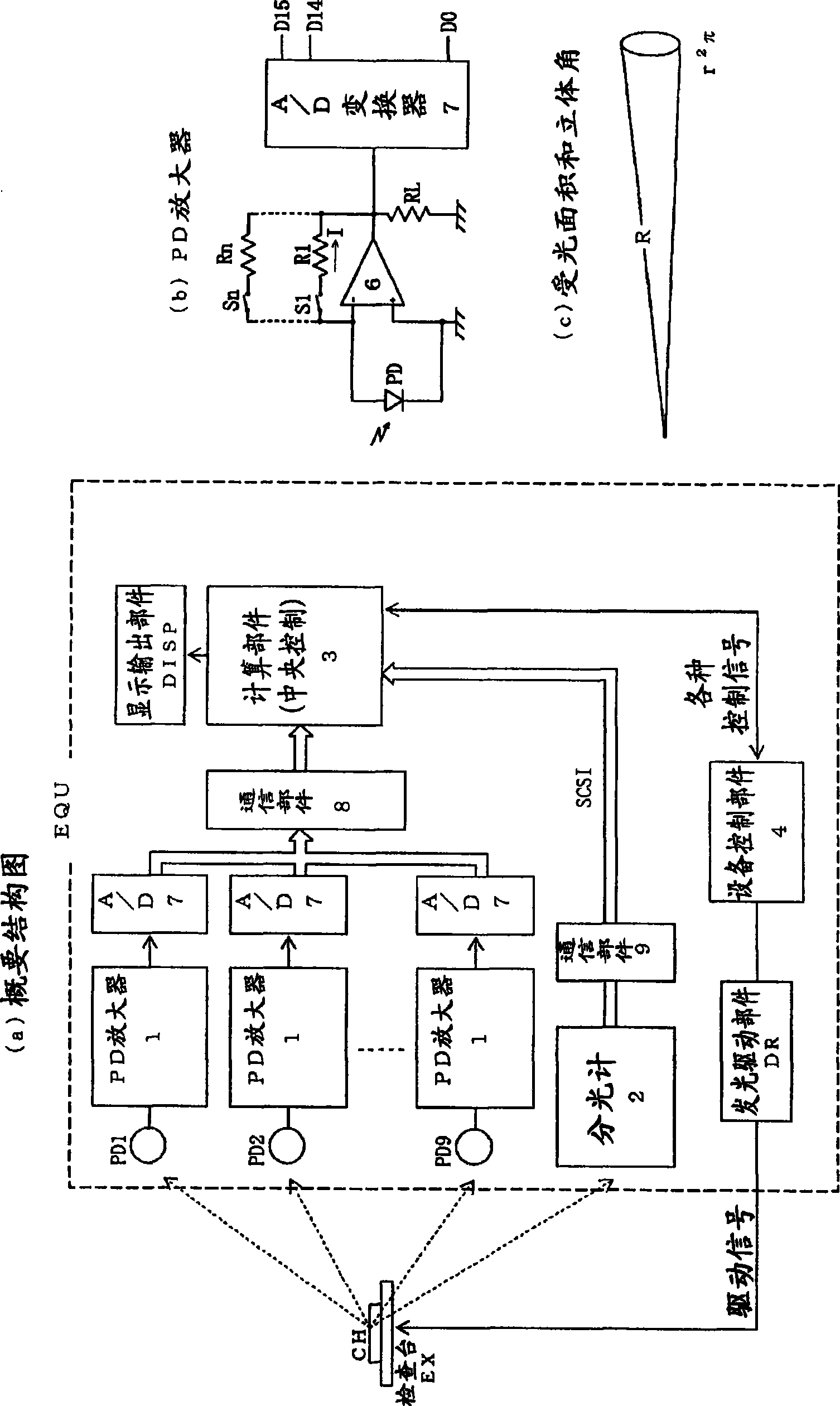
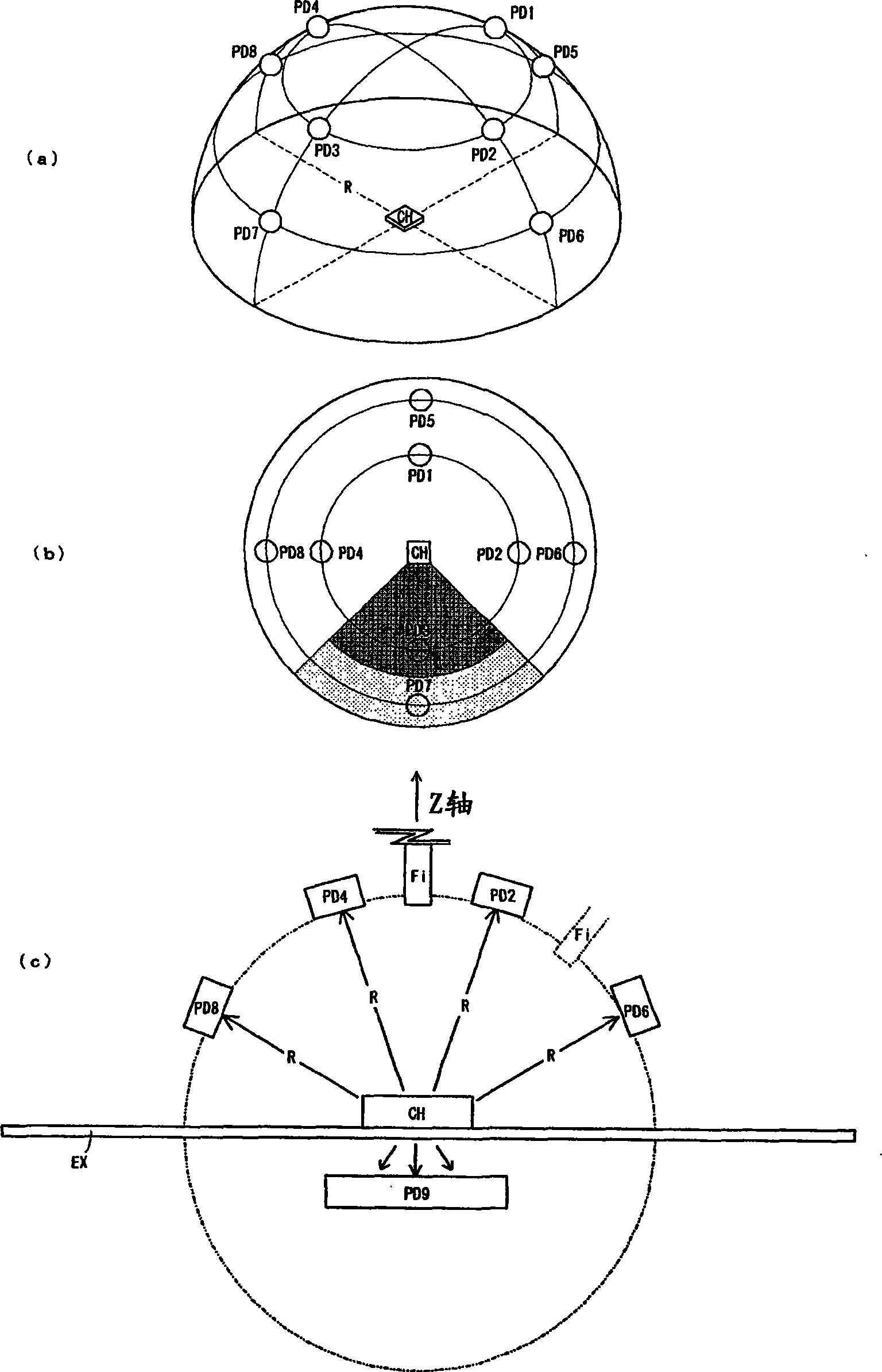
[0032] Hereinafter, the present invention will be described in more detail based on examples. figure 1 (a) is a circuit block diagram showing a schematic configuration of the photometry device EQU of the embodiment. In this photometry device EQU, a light-emitting element chip CH to be inspected is placed on an inspection table EX made of translucent glass, and is driven to turn on. Then, through the light metering device EQU, automatically calculate its luminous characteristics and output.

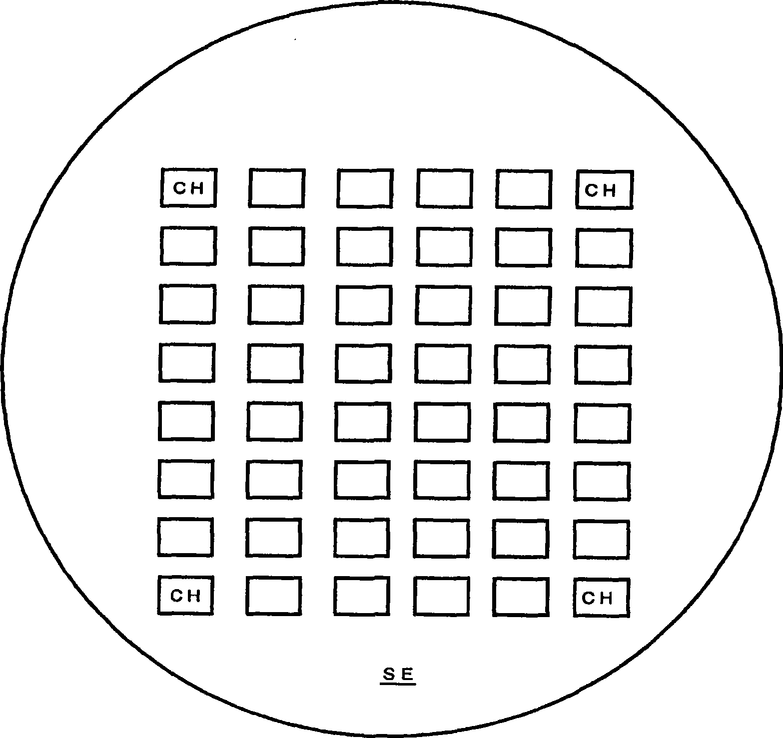
[0033] The light emitting element chip CH is, for example, a semiconductor chip constituting a light emitting diode. In addition, the plurality of light-emitting element chips CH...CH cut out by cutting the semiconductor wafer are held on the adhesive sheet SE and stand by ( image 3 ). In addition, a robot hand takes out the light-emitting element chips CH in the standby state one by one, and places them on the inspection table EX.

[0034] The light-emitting element chip has a light ...


PUM


Abstract

The invention discloses a light measuring device of a luminophor comprising: n light interception members for outputting and receiving detection data (Ii) corresponding to a light reception strength; a spectral analysis member for outputting spectral distribution data (P(lambada)) of the receiving light; a storage member corresponding to n interception members for respectively storing spectral sensitivity data (PDi(lambada)) of a light interception member sensitivity; and a control member executing an operation action. The control member comprises: a first treatment for calculating the spectral distribution (EGi(lambada)) of the lumiophor transmit power according to n detection data (Ii), n spectral sensitivity data (PDI(lambada)) and the spectral distribution data (P(lambada)); a second treatment for calculating a radiant flux (EGi) according to the spectral distribution (EGi(lambada)); and a third treatment for calculating a light flux (theta i) according to the spectral distribution (EGi(lambada)) and a spectral visible efficiency (V(lambada)). The light measuring device of the invention can fast and high precisely measure the light quantity for the luminophor with uneven lighting distribution.

Description

technical field [0001] The present invention relates to a photometric device capable of quickly and accurately determining light emission characteristics of light emitting element chips constituting LEDs (Light Emitting Diodes), LDs (Laser Diodes), etc. regardless of light distribution characteristics that differ from chip to chip. Background technique [0002] Manufacturers of LEDs and the like must measure the light quantity (quantity of light) of each light emitting element chip as part of final inspection. As the light quantity value, for example, luminous intensity (Luminous intensity) is required. Here, the candela value of luminous intensity Iγ is the ratio per unit solid angle dΩ to the lumen value of luminous flux Φγ, given by Iγ=dΦγ / dΩ. [0003] On the other hand, the luminous flux Φγ is the value of the weighted integral of the radiant flux Φe (radiant flux) using the standard Spectral Luminous efficiency (Spectral Luminous efficiency) V(λ) stipulated by CIE (Int...

Claims


Application Information

Patent Timeline
Patent Type & Authority Applications(China)
IPC IPC(8): G01J1/00G01J1/42G01J3/28G01M11/02G01M11/00H01L33/00
Inventor 池田研一保坂一铃木俊克井久保学
Owner オプトシステム
Why Eureka
Try Eureka