Time-delay reset control circuit and method

A delay reset and control circuit technology, applied in data reset device, hardware monitoring, data processing power supply, etc., can solve problems such as weak anti-interference ability, important data destruction in electric energy meter, CPU reset, etc.

Active Publication Date: 2009-07-01
ZHUHAI ZHONGHUI MICROELECTRONICS
View PDF0 Cites 23 Cited by
  • Summary
  • Abstract
  • Description
  • Claims
  • Application Information

AI Technical Summary

Problems solved by technology

However, while the existing reset control chip brings convenience to system circuit design, it also gradually exposes some application defects. The flexibility of its application is limited, and at the same time, it has a great impact on the stability of the system using the reset chip Impact
The following uses the application of the reset chip MAX706 in the electric energy meter as an example to illustrate. When the MAX706 is powered on or powered off, its output terminal will output a reset signal, and the MAX706 itself cannot control the time of the reset signal output. Therefore, when the electric energy meter During the process of detecting the power-off signal and storing data, the CPU may be reset and lose important data such as power
In addition, the existing reset chip has no power-off notification function, and the anti-interference ability is not strong. When the intelligent control system of the electric energy meter is frequently powered on and off, or the power supply interference signal is very large, it is easy to cause the electric energy meter to reset repeatedly, resulting in The destruction of important data seriously affects the reliable and normal operation of the energy meter
The defects in the application of the above-mentioned MAX706 also exist in other existing watchdog chips

Method used


Image

  • Time-delay reset control circuit and method
  • Time-delay reset control circuit and method
  • Time-delay reset control circuit and method

Examples


Embodiment Construction

[0028] The present invention will be further described in detail below in conjunction with the accompanying drawings and specific embodiments.

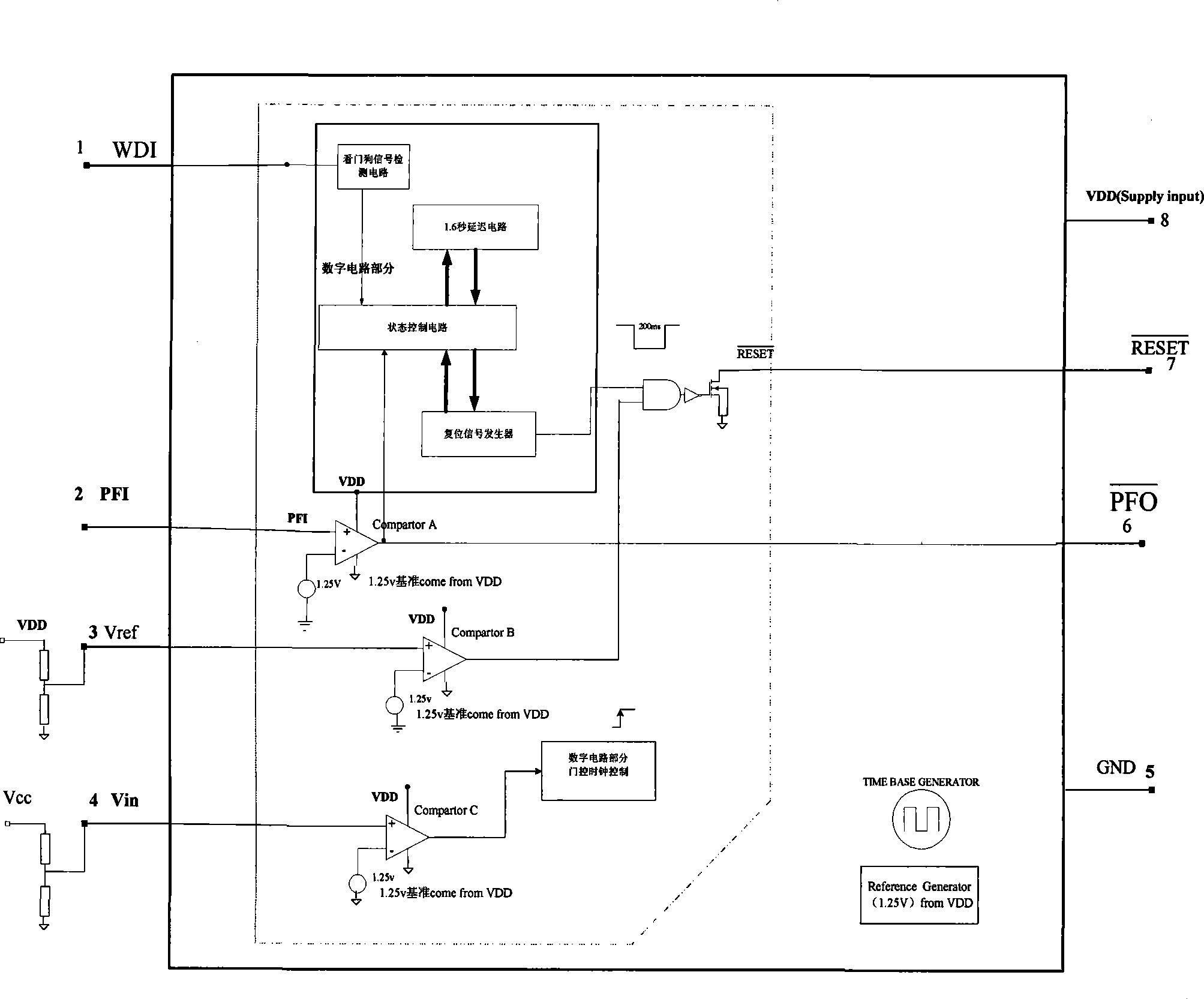
[0029] Such as figure 1 As shown, the delay reset control circuit disclosed in this embodiment is characterized in that it includes: a clock signal generation circuit, a watchdog signal detection circuit, a state control circuit, a timing delay circuit, a reset control circuit, a comparator A, a comparator B. AND gate, comparator C and gate control circuit.

[0030] The clock signal generation circuit oscillates to generate a pulse signal, which is input to the counter of the given timing delay circuit. The input terminal of the watchdog signal detection circuit is connected to the CPU, and the output is connected to the state control circuit, which is used to detect the watchdog input signal WDI, and after processing, send the feeding dog signal (the signal after detecting the inversion of the watchdog input signal) to the state Co...


PUM


Abstract

The invention relates to a time-delay reset control circuit and a time-delay reset control method. The time-delay reset control circuit has functions of a watchdog, and the time-delay reset control method is characterized in that when the system is electrified normally, an electrifying reset signal is output in delayed time, when the system operates abnormally, a reset signal is provided and a power-down notifying signal can be provided, wherein a certain time interval is guaranteed between the power-down notifying signal and the actual power down, thereby ensuring time for storing data when power is down and avoiding outputting the reset signal during the power down process. Besides, the invention provides a forced reset function, and when power voltage is lower than a reference voltage value, forced reset signals are maintained to keep the system to operate stably. Simultaneously, the invention further provides an energy-saving mode, and when the system power reference voltage is lower than a reference voltage value, a clock signal generator circuit is closed, thereby reducing power consumption. To sum up, the invention enables the system to run stably and reliably and to process data timely to avoid data loss.

Description

technical field [0001] The invention relates to a realization scheme of a reset function in systems such as electronic information, intelligent control, and signal processing, and in particular relates to a delay reset control circuit and a delay reset control method. Background technique [0002] In digital signal processing systems, reset processing is the most basic and extremely critical part. Reset is to initialize the sequential devices held in the circuit, so as to initialize the state of the circuit. When designing the circuit system, each system needs to have a control unit that can correctly reset the entire system. When the system is powered on or crashes, it can reset the CPU and other circuits with reset functions in the system. [0003] When designing the circuit system, a dedicated reset chip is generally installed in the system. The dedicated reset chip combines with peripheral circuits to form a reset control circuit. The reset control circuit outputs a res...

Claims


Application Information

Patent Timeline
Patent Type & Authority Applications(China)
IPC IPC(8): G06F1/24G06F1/30G06F11/30G06F1/32
CPCY02B60/165Y02D10/00
Inventor 史谦唐振中
Owner ZHUHAI ZHONGHUI MICROELECTRONICS
Why Eureka
Try Eureka