
While-drilling borehole compensation electromagnetic wave resistivity survey apparatus

A measuring device and electromagnetic wave technology, applied in electromagnetic wave detection, electric/magnetic detection for well logging records, wellbore/well components, etc., can solve the problems of difficult implementation, complex software focusing algorithm, and algorithm structure dependence Large and other problems, to achieve the effect of not affecting the drilling speed, reducing manufacturing costs, and avoiding instrument bending

Active Publication Date: 2009-07-15
SINOPEC SSC +3
View PDF0 Cites 35 Cited by
  • Summary
  • Abstract
  • Description
  • Claims
  • Application Information

AI Technical Summary

Problems solved by technology

This software calculation compensation method can realize complete wellbore compensation, but the software focusing algorithm is complex, and the accuracy of the algorithm is highly dependent on the structure of the coil system, so it is difficult to realize

Method used


Image

  • While-drilling borehole compensation electromagnetic wave resistivity survey apparatus
  • While-drilling borehole compensation electromagnetic wave resistivity survey apparatus
  • While-drilling borehole compensation electromagnetic wave resistivity survey apparatus

Examples


Embodiment Construction

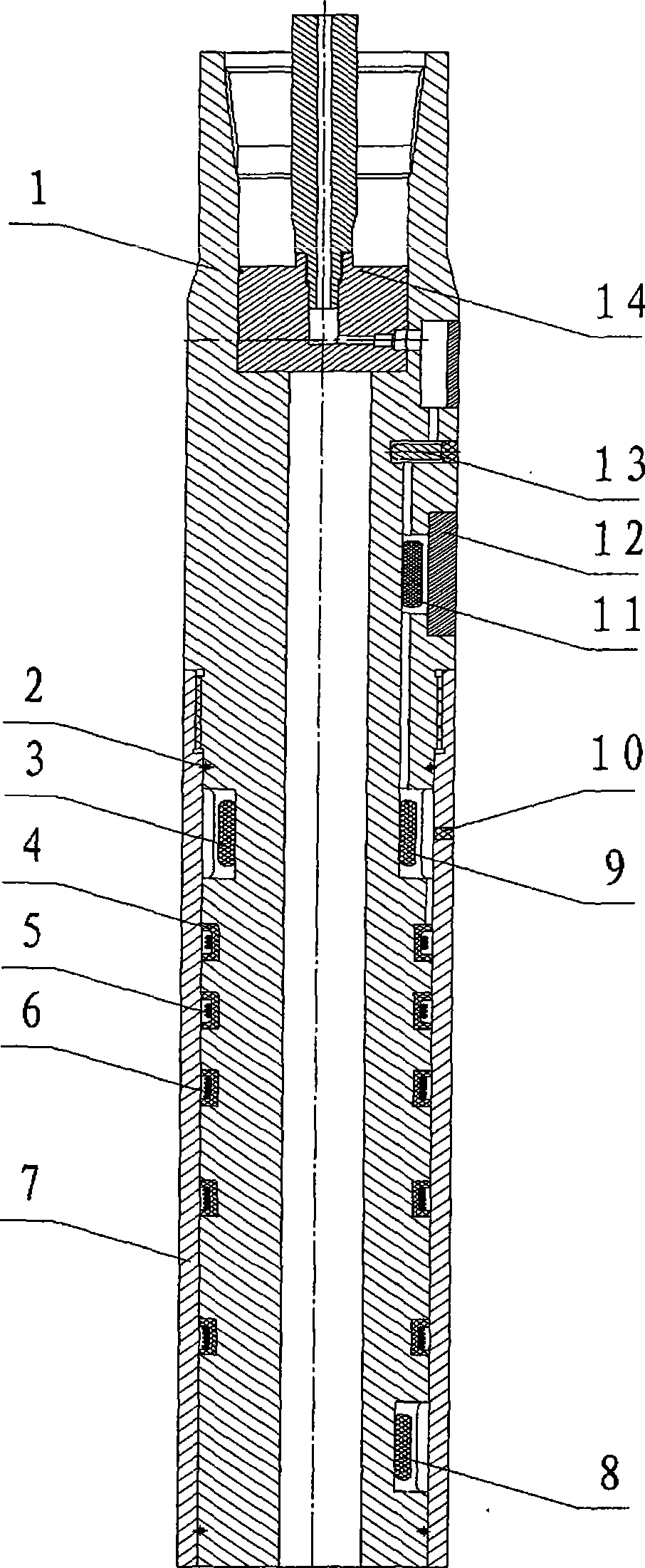
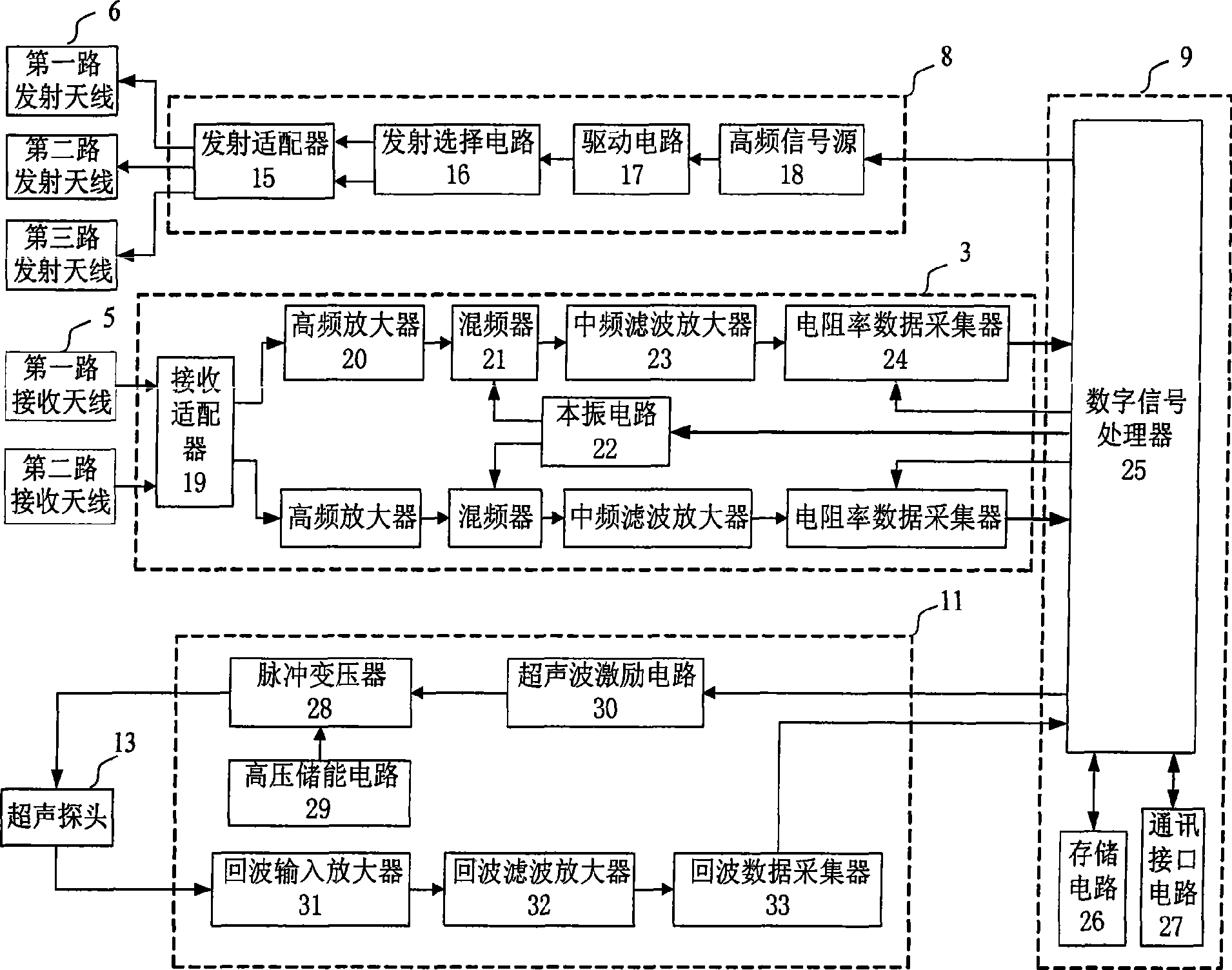
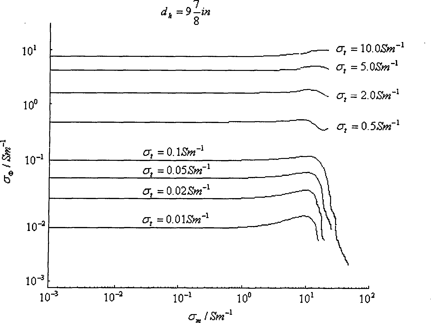
[0024] Now combined with the manual figure 1 , 2 , 3, further describe the present invention.

[0025] figure 1 It shows an axial section view of a measuring device for borehole compensation electromagnetic wave resistivity while drilling. The drill collar 1 is the installation skeleton of the measuring device and a part of the downhole drilling tool. From the middle position of the drill collar 1 to the lower end, a part of the surface is uniformly milled off to form a small-diameter section of the drill collar and a large-diameter section of the drill collar. An external thread is processed at the root of the drill collar thin section, which is used to protect the connection of the sleeve 7 . A sealing ring 2 is installed at the lower part of the external thread and the lower end of the drill collar's thin diameter section to protect the sealing of the inner parts of the sleeve 7 .

[0026] In the middle part of the drill collar narrow section, a plurality of bobbins 4 ...


PUM

PropertyMeasurementUnit
Resonant frequencyaaaaaaaaaa

Abstract

A borehole compensation electromagnetic wave resistivity measuring device while drilling uses a transmitting antenna which is at one side of a receiving antenna and has a non-symmetric coil system with different spacing, and sleeves the non-symmetric coil system and a measuring circuit on a drilling collar for obtaining a strata resistivity measurement value with a plurality of detecting depths; moreover, an ultrasonic probe and the measuring circuit are installed on the drilling collar for measuring the diameter of a borehole, and compensating and modifying the strata resistivity measurement value according to the relationship among the resistivity measurement value and the diameter of the borehole and the electrical conductivity of slurry, thereby achieving accurate measurement of the strata resistivity. Therefore, not only the length of the measuring device is shortened, the manufacturing cost is reduced, and the occurrence for the bending of the instrument and the clamping of the drill in a highly-deviated well or a branch well with small curvature radius is avoided, but also the real-time borehole compensation function is achieved, and the drilling speed is not affected; the invention is good for adjusting the well trajectory in time in a highly-deviated well or a horizontal well and controlling the drilling tool to pass through the best position in a reservoir according to the geological information.

Description

Technical field: [0001] The invention relates to the fields of oil drilling and well logging, in particular to the resistivity logging technology while drilling, and in particular to a measuring device for borehole compensation electromagnetic wave resistivity while drilling. Background technique: [0002] In geosteering drilling and logging while drilling in the petroleum industry, the formation resistivity is usually obtained by the electromagnetic wave resistivity measuring device while drilling, which is used to divide the formation section, identify the oil and gas layers, and determine the oil saturation of the reservoir. The main basis for oil and gas storage. [0003] At present, the known electromagnetic wave resistivity measurement device while drilling usually adopts a coil system with multiple transmitting coils and receiving coils. Using the principle of electromagnetic wave propagation, the transmitting coils transmit electromagnetic waves at different operatin...

Claims


Application Information

Patent Timeline
IPC IPC(8): E21B49/00G01V3/12G01V3/18
Inventor 杨锦舟肖红兵张海花
Owner SINOPEC SSC
Learn More