Stirling engine
A Stirling engine and ring-shaped technology, applied in the direction of machines/engines, hot gas variable displacement engine devices, mechanical equipment, etc., can solve the problems that restrict the development and application of Stirling engines, high prices, and limited resources
- Summary
- Abstract
- Description
- Claims
- Application Information
AI Technical Summary
Problems solved by technology
Method used
Image

Examples
specific Embodiment approach 2
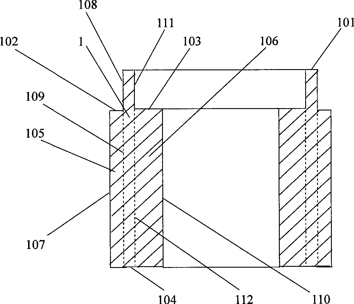
[0048] Along the downward direction of the height of the annular outer stepped column 105 , a wave-shaped groove is dug on the annular outer stepped column 105 , which is called the outer wave-shaped groove 1051 for short. The center line of groove symmetry of the outer corrugated groove 1051 is a wave line, the length of its major axis is equal to the height of the annular outer stepped column 105, and the length of its minor axis is equal to the fluctuation amplitude of the outer wave groove 1051. Excavating the outer corrugated groove 1051 on the annular outer stepped column 105, its minor axis intersects with the circumferential surface of the annular outer stepped column 105 diameter, the opening 1052 of the outer wave groove 1051 is positioned on the circumferential surface of the annular outer stepped column 105 diameter, it The depth is close to the inner diameter curved surface 109 of the annular outer step 102, and its wave surface is perpendicular to the circumferent...
specific Embodiment approach 3
[0050] Along the downward direction of the height of the annular inner stepped column 106 , a wave-shaped groove is dug on the annular inner stepped column 106 , which is called the inner wave-shaped groove 1061 for short. The groove symmetry center line of the inner wave groove 1061 is a wave line, the length of its major axis is equal to the height of the annular inner step column 106, and the length of its minor axis is equal to the fluctuation range of the inner wave groove 1061. The inner wave groove 1061 excavated on the annular inner stepped column 106, its short axis intersects with the circumferential surface of the inner diameter of the annular inner stepped column 106, the opening 1062 of the inner wave groove 1061 is located on the inner diameter curved surface 110 of the annular inner stepped column 106, its The depth is close to the circular inner step 103 diameter curved surface 112, and its wave surface is perpendicular to the circumferential surface of the inne...
specific Embodiment approach 4
[0052] The long axis of the excavated outer corrugated groove surrounds the curved surface of the inner diameter of the annular outer step according to a certain helical angle, so that the upper end and lower end of the outer corrugated groove differ by a certain angle in the direction of the circumferential line of the inner diameter curved surface of the annular outer step to form a spiral outer waveform Groove; the groove symmetry center line of the spiral outer wave groove is a spiral wave line, the spiral axis line of the spiral outer wave groove coincides with the axis line of the hollow cylinder, and the same number of spiral outer wave grooves as the spiral outer wave groove are uniform, Alternately distributed on the annular outer steps; the gas working medium reciprocates in the spiral outer wave groove following the movement of the piston, and the flowing gas working fluid scours the wave surface of the spiral outer wave groove in the direction of its flow, and from t...
PUM
 Abstract
Description
Claims
Application Information
 - R&D
- Intellectual Property
- Life Sciences
- Materials
- Tech Scout
- Unparalleled Data Quality
- Higher Quality Content
- 60% Fewer Hallucinations
Browse by: Latest US Patents, China's latest patents, Technical Efficacy Thesaurus, Application Domain, Technology Topic, Popular Technical Reports.
© 2025 PatSnap. All rights reserved.Legal|Privacy policy|Modern Slavery Act Transparency Statement|Sitemap|About US| Contact US: help@patsnap.com