Asynchronous magnetic couplings for high temperature resistant high performance oblique slot type rotor

A magnetic coupling, high-performance technology, applied in the direction of permanent magnet clutch/brake, etc., can solve the problems of increased rotor loss, reduced efficiency, and small distribution difference, etc., to achieve increased transmission torque, stable and reliable operation, The effect of high transmission efficiency

Inactive Publication Date: 2009-07-15
JIANGSU UNIV
View PDF1 Cites 34 Cited by
  • Summary
  • Abstract
  • Description
  • Claims
  • Application Information

AI Technical Summary

Problems solved by technology

[0003] Chinese patent 200420025250.2 discloses a permanent magnet induction magnetic transmission device. Since the inner rotor does not need permanent magnet materials, it can meet the transmission requirements at high temperature, but the above-mentioned magnetic transmission cannot provide a stronger high-speed rotating magnetic field due to its permanent magnets. In addition, the inner rotor is embedded The radial depth of the strip conductor is small, and the induced current and the distribution of the magnetic force lines generated in

Method used


Image

  • Asynchronous magnetic couplings for high temperature resistant high performance oblique slot type rotor
  • Asynchronous magnetic couplings for high temperature resistant high performance oblique slot type rotor
  • Asynchronous magnetic couplings for high temperature resistant high performance oblique slot type rotor

Examples


Embodiment Construction

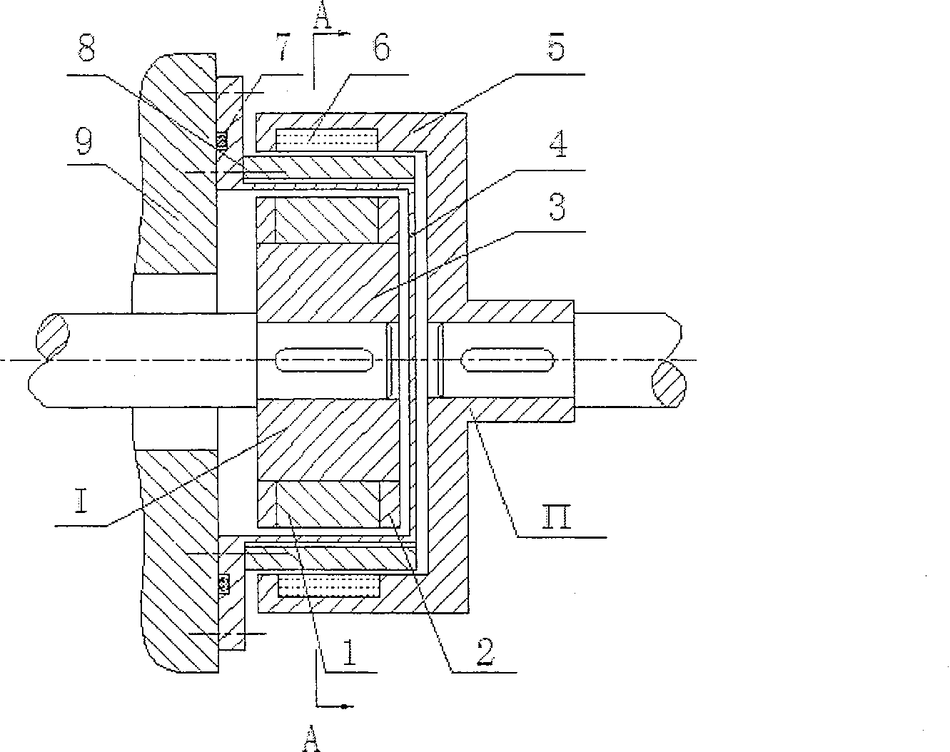
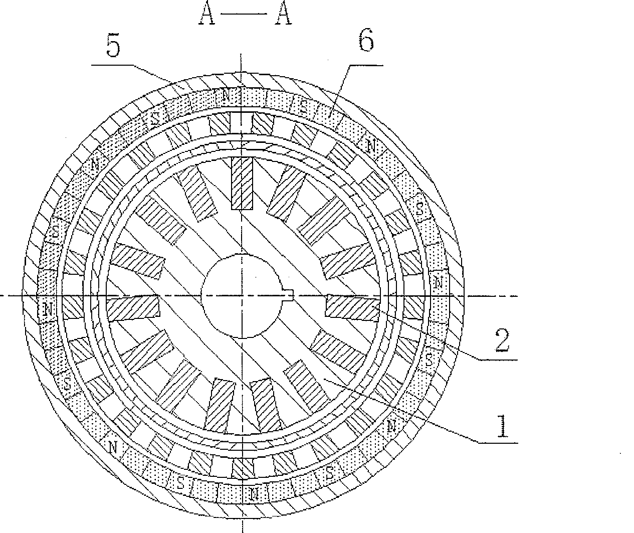
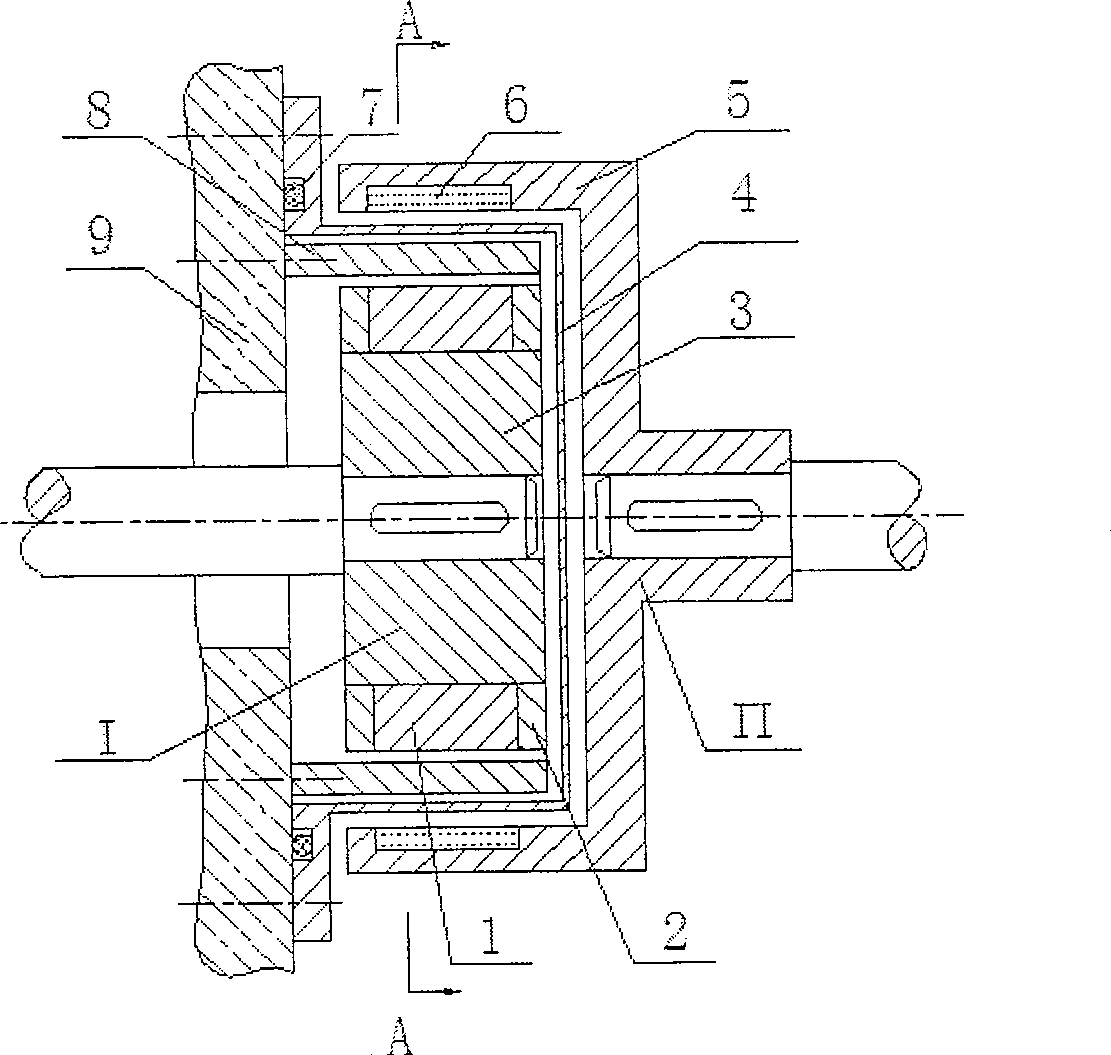
[0027] The overall structure of the present invention is as figure 1 As shown, the device includes: an outer rotor composed of an outer rotor base body 5 and an outer rotor permanent magnet 6, an inner rotor composed of an inner rotor base body 3, a magnetic induction conductor and an end ring 2, a sealed spacer sleeve 4 and a toothed magnetic pole slice 8. The sealing spacer 4 is placed between the inner rotor and the outer rotor, and the cover is installed on the inner rotor. The toothed magnetic pole piece 8 is placed between the inner rotor and the outer rotor, and fixed on the body 9 with screws. There are two ways to place it: one is to place it tightly outside the sealing spacer 4 and close to the outer rotor base 5, The other is placed in the sealing spacer 4 and close to the inner rotor base 3 . The outer rotor is composed of an outer rotor base body 5 and an outer rotor permanent magnet 6. The outer rotor permanent magnets 6 are closely arranged in an even number ...


PUM


Abstract

The present invention relates to technical field of magnetic transmission in mechanical engineering, particularly a high temperature resistant high performance tapered slot type rotor asynchronous magnetic coupling, which comprises an outer rotor with magnetism, a inner rotor without magnetism, separation sleeve, and adjustable magnetic pole piece with teeth; the outer rotor comprises an outer rotor basal body and magnetic pole; the magnetic pole forms a certain helix angle with axial cord; the inner rotor comprises a inner rotor basal body, a magnetic induction prime conductor and end rings; the magnetic induction prime conductor embeds in angular deep groove of the inner rotor basal body in helical shape; the separation sleeve covers the inner rotor and is set between the inner rotor and the outer rotor; the adjustable magnetic pole piece with teeth is fixed on the machine body and can be disposed inside or outside of the separation sleeve; the outer magnetic rotor forms an outer layer air gap with the adjustable magnetic pole piece; the inner rotor forms an inner layer air gap with the adjustable magnetic pole piece. The above structure is disposed on the inside and outside circular conical surface to form circular cone asynchronous magnetic transmission. The advantages of the invention are as following: high temperature resistant, smooth, steady and reliable transmission, high usage of permanent magnet and big transmitting torque of unit volume.

Description

technical field [0001] The invention relates to the technical field of magnetic transmission in mechanical engineering, in particular to a magnetic field modulated high-performance, high-temperature-resistant chute rotor asynchronous magnetic coupling. It is mainly used in transmission devices or equipment with high working temperature and non-leakage requirements in the production environment, especially suitable for magnetic pumps, magnetic stirring tanks, magnetic valves, etc. without shaft seals, leak-free, and high temperature resistance. Background technique [0002] Traditional mechanical couplings are widely used in mechanical transmission connections, and generally use contact to transmit motion and power, which has disadvantages such as large impact, short life, and need for lubrication. At present, the commonly used synchronous magnetic transmission device works according to the principle of repulsion of the same sex and attraction of opposite sex, so the inner an...

Claims


Application Information

Patent Timeline
IPC IPC(8): H02K49/10
Inventor 杨超君蒋毅一
Owner JIANGSU UNIV
Why Eureka
Try Eureka