Power system with air as energy source

A power system and air engine technology, applied in the field of power system, can solve problems such as hidden safety hazards, hydropower drop, and difficulty in commercialization.

Active Publication Date: 2009-07-22
陈伯元 +4
View PDF1 Cites 16 Cited by
  • Summary
  • Abstract
  • Description
  • Claims
  • Application Information

AI Technical Summary

Problems solved by technology

[0002] Traditional thermal power, hydraulic power, and wind power generation have their own disadvantages. For example, thermal power generation needs to consume a large amount of primary energy—coal or oil; hydropower generation requires a drop in water level; wind power generation is restricted by the natural environment and The most effective areas such as high altitudes, open areas, and valleys that can gather wind power must be sparsely populated, mountainous or coastal areas, far away from residential areas, industrial centers, and cities that require electric energy, so there are still problems with power transmission.
The compressed air of One CAT is consumed like fuel oil during the working process, and the compressed air needs to be replenished. One CAT can be refilled at a dedicated "gas station", which needs to be equipped with a specia...

Method used


Image

  • Power system with air as energy source
  • Power system with air as energy source
  • Power system with air as energy source

Examples


Embodiment 1

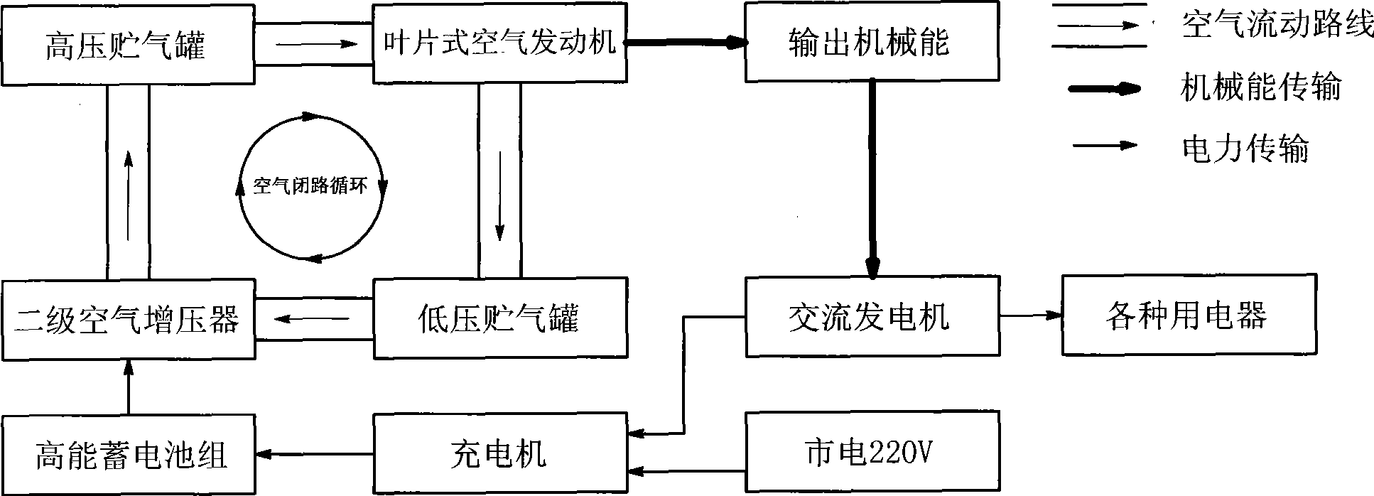
[0029] see figure 1 , this embodiment includes an air closed-loop circulation system composed of a high-pressure air storage tank, an air engine, a low-pressure air storage tank and a secondary air supercharger. The compressor is connected in sequence through a hose with a pressure resistance of 3.0Mpa to form a closed loop, in which the high-pressure air storage tank is connected to the air inlet of the air engine, the low-pressure air storage tank is connected to the exhaust port of the air engine, and the output shaft of the air engine outputs mechanical energy. To the alternator, the energy of the secondary air booster is provided by a high-energy storage battery pack, and the high-energy storage battery pack is supplied with electric energy by an alternator or 220V mains through a charger.

[0030] The high-pressure air storage tank and the low-pressure air storage tank are air storage tanks, the secondary air booster is an air compressor powered by a DC motor (replacing ...

Embodiment 2

[0040] see Figure 5 , this embodiment includes an air closed-loop circulation system composed of a high-pressure air storage tank, an air engine, a low-pressure air storage tank and a secondary air supercharger. The compressor is connected in sequence through a hose with a pressure resistance of 3.0Mpa to form a closed loop, in which the high-pressure air storage tank is connected to the air inlet of the air engine, the low-pressure air storage tank is connected to the exhaust port of the air engine, and the output shaft of the air engine outputs mechanical energy. To the transmission mechanism, and then the transmission mechanism drives the wheel assembly with the rear axle. The energy of the secondary air booster is provided by the high-energy battery pack, and the high-energy battery pack provides electric energy from the 220V mains through the charger.

[0041] The high-pressure air storage tank and the low-pressure air storage tank are air storage tanks, the secondary ai...


PUM


Abstract

The invention discloses a dynamical system, in particular relates to an air energy dynamical system which adopts the air as the energy. The air energy dynamical system includes a high-pressure air holder which forms closed cycle through pipeline connection, an air engine, a low-pressure air holder and a secondary air booster, wherein, the high-pressure air holder is connected with an air inlet of the air engine; the low-pressure air holder is connected with an air exhaust of the air engine; an output shaft of the air engine outputs mechanical energy; and the energy of the secondary air booster is provided by a high-energy accumulator battery. The secondary air booster is an air compressor which adopts a direct current motor as the power. The invention has the advantage of taking air as energy without environmental pollution and having simple structure, high safety performance and closed cycle.

Description

technical field [0001] The invention relates to a power system, in particular to an air energy power system using air as energy. Background technique [0002] Traditional thermal power, hydraulic power, and wind power generation have their own disadvantages. For example, thermal power generation needs to consume a large amount of primary energy—coal or oil; hydropower generation requires a drop in water level; wind power generation is restricted by the natural environment and The most effective areas such as high altitudes, open areas, and valleys that can gather wind power must be sparsely populated, mountainous or coastal areas, far away from residential areas, industrial centers, and cities that require electric energy, so there are still problems with power transmission. . [0003] In addition, the current large increase in automobiles has brought about a large amount of energy consumption and environmental pollution. Most of the existing automobiles use oil as energy. ...

Claims


Application Information

Patent Timeline
IPC IPC(8): F01C1/344F01C13/00F01B29/10F01B23/02B60K8/00
CPCB60K8/00
Inventor 陈伯元
Owner 陈伯元
Why Eureka
Try Eureka