
Major-minor cylinder combined engine

A technology of engine and auxiliary cylinder, which is applied in the field of combined engine of main and auxiliary cylinders, can solve the problems that the thermal energy efficiency is far from the theoretical value, it is difficult to achieve complete combustion of fuel, and the emission of harmful substances is large, so as to improve the effective thermal efficiency and reduce the manufacturing cost , the effect of less pollution discharge

Inactive Publication Date: 2009-07-22
孙国繁
View PDF0 Cites 1 Cited by
  • Summary
  • Abstract
  • Description
  • Claims
  • Application Information

AI Technical Summary

Problems solved by technology

Each cylinder of the internal combustion engine performs a working cycle of "intake → compression → work → exhaust". This cycle leads to low effective thermal efficiency, high fuel consumption, and high emissions of harmful substances such as carbon dioxide.
On the basis of traditional technology, multi-valve and overhead camshaft, turbocharging, variable valve timing and dual spark plugs, in-cylinder direct injection and variable intake manifold length, electronically controlled common rail direct Modern technologies such as fuel injection have improved thermal efficiency, reduced fuel consumption and emissions of harmful substances such as carbon dioxide. However, due to the intermittent combustion of fuel in the internal combustion engine, and each combustion cycle is very short, each combustion cycle It is difficult to achieve the complete combustion of fuel, which will inevitably lead to the discharge of non-combustion and partially combusted fuel from the internal combustion engine, which makes the thermal energy efficiency of the fuel far from the theoretical value, and the pollutant ratio in the exhaust gas is quite high

Method used


Image

  • Major-minor cylinder combined engine

Examples


Embodiment Construction

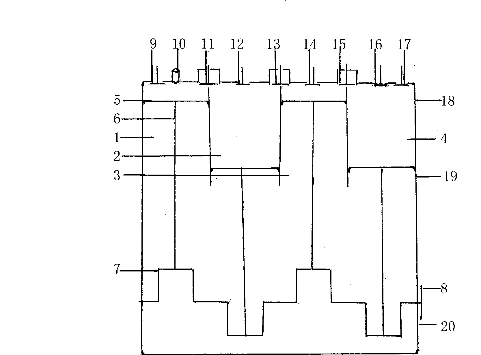
[0017] The combined main and auxiliary cylinder engine of the present invention consists of a cylinder body 19, a cylinder cap 18, an oil pan 20, a master cylinder 1, a first auxiliary cylinder 2, a second auxiliary cylinder 3, a third auxiliary cylinder 4, a piston 5, and a connecting rod 6 , crankshaft 7, main cylinder intake valve 9, spark plug or diesel high-pressure injector 10, main cylinder 1 and first auxiliary cylinder 2 upper exhaust intake valve 11, first auxiliary cylinder 2 intake valve 12, first auxiliary cylinder Exhaust intake valve 13 on cylinder 2 and the upper part of the second auxiliary cylinder 3, intake valve 14 on the second auxiliary cylinder 3, exhaust intake valve 15 on the upper part of the second auxiliary cylinder 3 and third auxiliary cylinder 4, third auxiliary cylinder 4 Intake valve 16, third secondary cylinder 4 exhaust valve 17, flywheel 8 and other components. The cylinder cap 18 seals the upper part of the cylinder body 19, the oil pan 20 ...


PUM


Abstract

The invention relates to a main and assistant cylinder combination engine which comprises a main cylinder, an assistant cylinder, a piston, a connecting rod, a crankshaft, an intake valve, an exhaust intake valve, an exhaust valve, a spark plug or a diesel high-pressure fuel injector and flywheel and the like. The main cylinder of the engine is injected with gas mixture, such as fuel and the like and burns and applies work, exhausts incompletely burnt high-temperature and high-pressure mixture gas into one assistant cylinder or a plurality of assistant cylinders to continue burn and apply work and finally the gas mixture are exhausted into the atmosphere after burning and applying work in the last assistant cylinder. Compared with the existing explosion engine, in the working cycle, the combination engine has prominent advantages of: 1 reducing the fuel consumption; 2 improving the effective thermal efficiency; 3 decreasing the pollutant emission and 4 simplifying the structure and reducing the manufacturing cost.

Description

technical field [0001] The invention relates to an engine, in particular to a combined main and auxiliary cylinder engine. Background technique [0002] At present, reciprocating piston internal combustion engines with gasoline, diesel oil, gas, etc. as fuels are widely used. Each cylinder of the internal combustion engine performs a working cycle of "intake air → compression → work → exhaust". This cycle leads to low effective thermal efficiency, high fuel consumption, and high emissions of harmful substances such as carbon dioxide. On the basis of traditional technology, multi-valve and overhead camshaft, turbocharging, variable valve timing and dual spark plugs, in-cylinder direct injection and variable intake manifold length, electronically controlled common rail direct Modern technologies such as fuel injection have improved thermal efficiency, reduced fuel consumption and emissions of harmful substances such as carbon dioxide. However, due to the intermittent combusti...

Claims


Application Information

Patent Timeline
Patent Type & Authority Applications(China)
IPC IPC(8): F02B75/20F02B75/02
Inventor 孙国繁
Owner 孙国繁
Learn More