Electro-optical range finder

A range finder, electro-optic technology, applied in the direction of measuring distance, radio wave measuring system, instrument, etc., can solve the problems of high heat load, applicability limitation, high energy consumption, etc., and achieve the goal of improving measurement speed, reducing complexity and reducing cost Effect

Inactive Publication Date: 2009-07-22
LEICA GEOSYSTEMS AG
View PDF7 Cites 17 Cited by
  • Summary
  • Abstract
  • Description
  • Claims
  • Application Information

AI Technical Summary

Problems solved by technology

However, such microchip solid-state lasers have the disadvantages of large size, high power consumption and poor operating characteristics such as due to thermal effects
Therefore, in practice, the applicability of this solution for use in site surveys is limited
[0013] Diode-pumped solid-state lasers meet the requirements in terms of beam quality and peak power, but are very complex in principle (pump laser with drive unit, entrance optics, amplification medium, mass circuit, resonator) and are very expensive
Furthermore, these solid-state lasers also generally do not allow a flexible adjustment of the pulse rate, since this is limited at low efficiencies due to the high thermal load

Method used


Image

  • Electro-optical range finder
  • Electro-optical range finder
  • Electro-optical range finder

Examples


Embodiment Construction

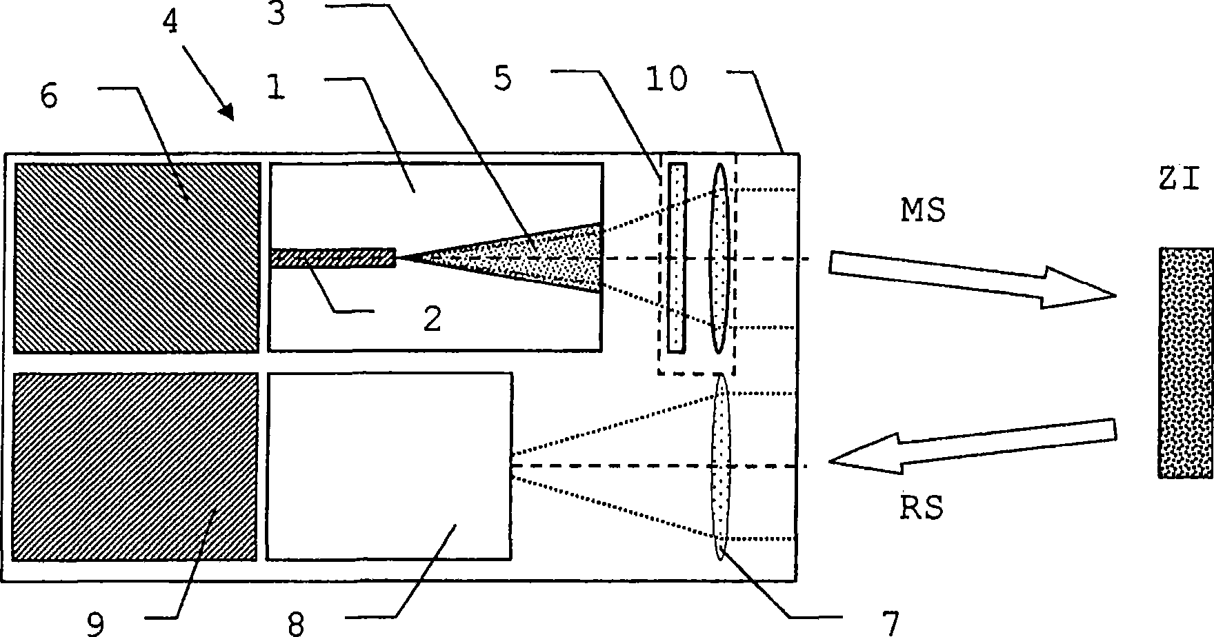
[0041] figure 1 The structure of a distance measuring device 4 with a tapered diode laser 1 is illustrated in a schematic diagram. The distance measuring device has a laser source control device 6 and a conical diode laser 1 for emitting a laser beam as the laser source of the emission optics 5 . The laser beam is emitted as a measuring beam MS to the target ZI to be surveyed, from where it is partially received as a reflected measuring beam RS by the receiving optics 7 and the detector 8, and is evaluated by the evaluation unit 9 for the distance to the target ZI The signal of the detector 8 is evaluated. According to the invention, the emission optics system 5 is designed to simultaneously compensate for influences due to different emission positions of the beam of the tapered diode laser 1 in the fast axis and the slow axis. Transmitting optics 5 thus performs astigmatism compensation and at the same time collimation of the laser beam.

[0042] Viewed on the slow axis, a...


PUM


Abstract

An electro-optical range finder (4) has a trapezoidal laser (1) as a laser source, a laser source controller (6) for generating pulsed laser radiation, receiving optics (7) and a detector (8) with an evaluation unit (9) for receiving and evaluating the measuring radiation (RS) reflected by a target (ZI), in order to measure distance, has a separate supply for the guided waveguide region (2) and the trapezoidal region (3) as well as transmitting optics (5) with astigmatism compensation and for collimating the laser radiation.

Description

technical field [0001] The invention relates to an electro-optical distance measuring device according to the preamble of claim 1, a measuring device with such a distance measuring device, and an electro-optical distance measuring device according to the preamble of claim 12 in which pulses are generated. Laser beam method. Background technique [0002] In many geodetic applications it is necessary or advantageous to emit laser light. This relates in particular to electro-optical distance measurement with a geodetic accuracy usually in the millimeter or submillimeter range, which can be achieved, for example, by means of the pulse transit time measurement principle or the phase measurement principle. Suitable methods and systems of this type for distance measurement are described, for example, in EP 0738 899 B1 or WO2004 / 074773. [0003] Geodetic applications require ranging over relatively large distances, which places high demands on the beam source. It is advantageous ...

Claims


Application Information

Patent Timeline
Patent Type & Authority Applications(China)
IPC IPC(8): G01C3/00G01C3/02G01S17/08G01S17/10
CPCG01S17/10G01S7/4814G01C3/08
Inventor 托马斯·延森彼得·基佩弗劳伦特·施陶费尔雷托·施图茨
Owner LEICA GEOSYSTEMS AG
Why Eureka
Try Eureka