
Method for coordinating interference between districts of relay wireless communication network

An inter-cell interference and coordination method technology, applied in wireless communication, transmission control/equalization, power management, etc., can solve the problem of decreased spectrum utilization, decreased throughput of user terminals at the edge of cells, decreased average throughput of user terminals, and reduced scheduling flexibility to improve user terminal throughput, improve flexibility, and ensure service quality

Inactive Publication Date: 2009-07-29
ZTE CORP
View PDF0 Cites 21 Cited by
  • Summary
  • Abstract
  • Description
  • Claims
  • Application Information

AI Technical Summary

Problems solved by technology

[0004] Using layered partial power control and path loss compensation methods, when the load in the wireless communication network is light or span load, the time-frequency resources used by each adjacent cell, that is, the Physical Resource Block (Physical Resource Block) can be guaranteed. , PRB) remain orthogonal, but when the load is relatively heavy, it is difficult to ensure that the time-frequency resources used between all adjacent cells remain orthogonal through scheduling, although it is possible to distinguish the time-frequency resources used in adjacent cells by setting sensitive areas The part with the highest collision probability in time-frequency resources is completely orthogonal, but it reduces the flexibility of scheduling and reduces the spectrum utilization rate during partial power control and path loss compensation, resulting in the throughput of user terminals at the cell edge and the average throughput of user terminals. decline in volume

Method used


Image

  • Method for coordinating interference between districts of relay wireless communication network
  • Method for coordinating interference between districts of relay wireless communication network
  • Method for coordinating interference between districts of relay wireless communication network

Examples


Embodiment Construction

[0068] The present invention will be described in further detail below in conjunction with the accompanying drawings and embodiments.

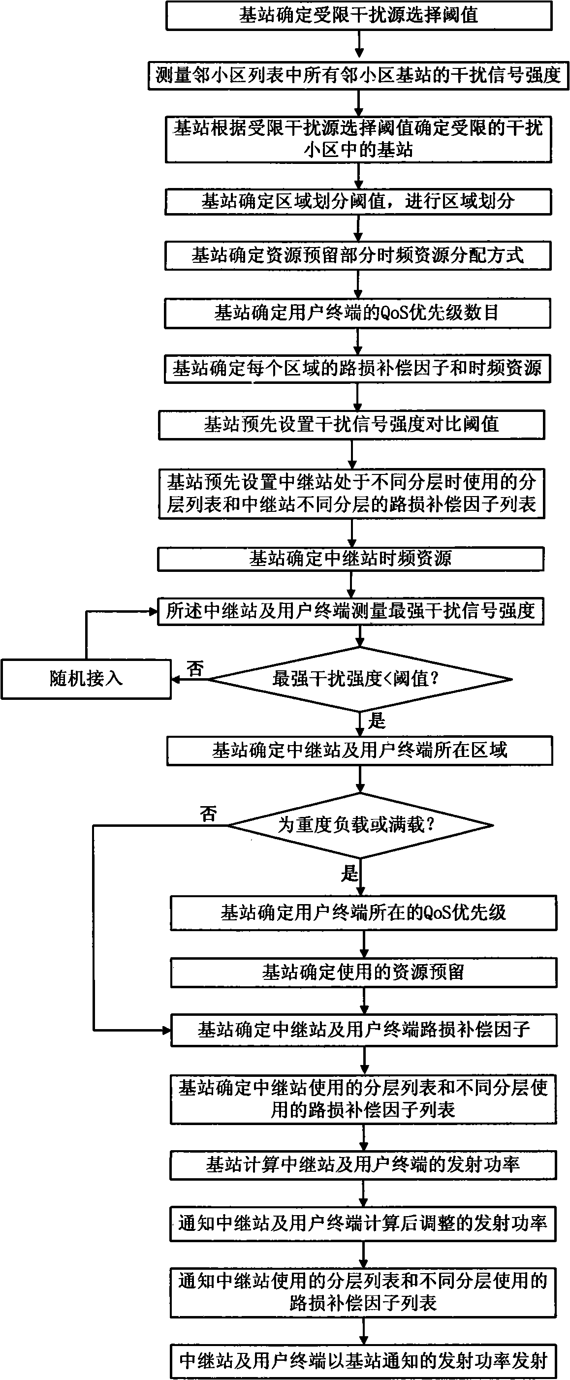
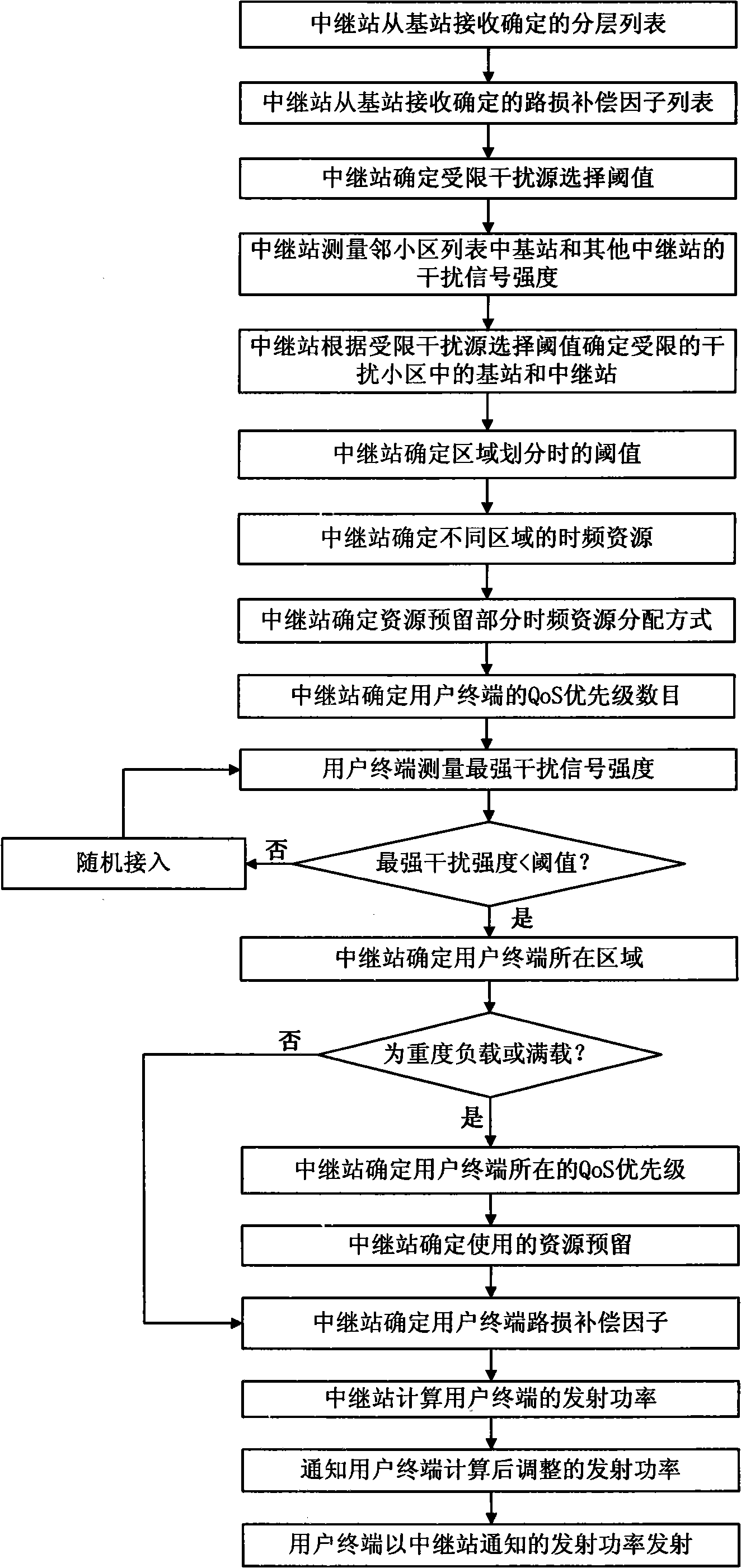
[0069] As shown in FIG. 1 , it is a flowchart for realizing the inter-cell interference coordination method of the present invention. Among them, FIG. 1(a) is a flow chart of base station interference coordination, and the steps are as follows:

[0070] Step 101a: the base station determines a threshold for selecting a restricted interference source;

[0071] Step 102a: the base station measures the interference signal strength of all neighboring cell base stations in the neighboring cell list;

[0072] Step 103a: the base station determines the base station in the restricted interfering cell according to the restricted interference source selection threshold;

[0073] Step 104a: the base station determines an area division threshold and performs area division;

[0074] Step 105a: the base station determines the time-frequency resource allo...


PUM


Abstract

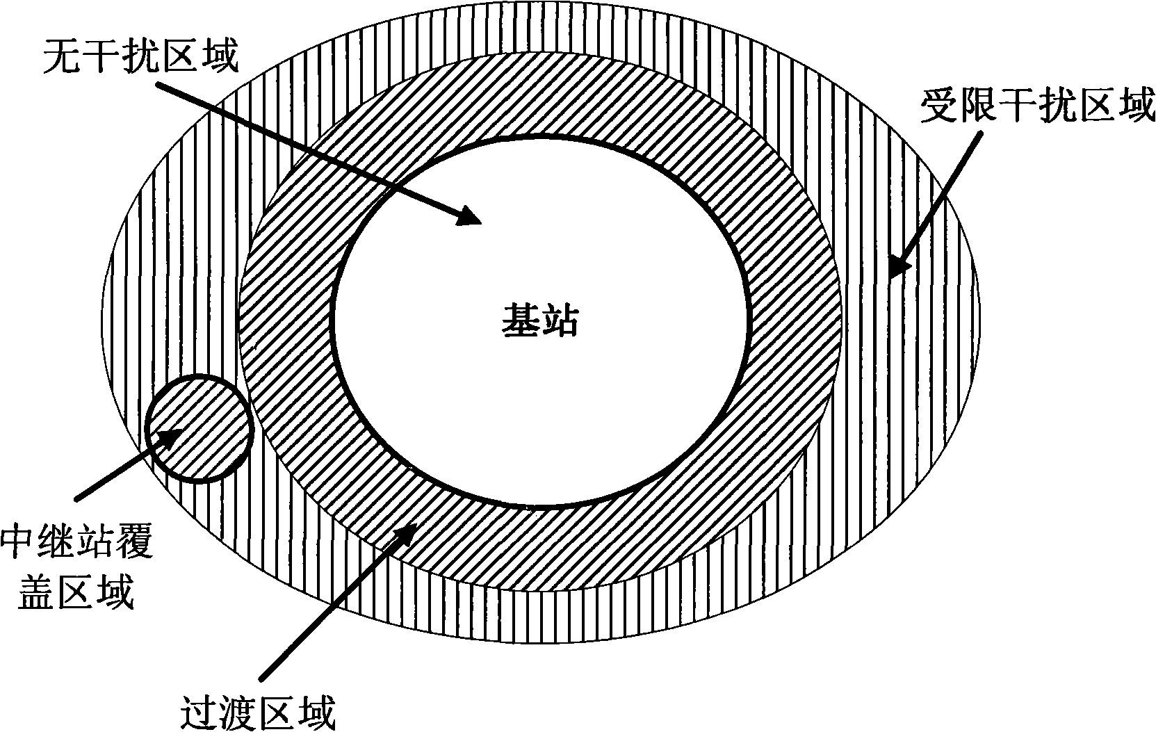
The invention relates to an inter-cell interference coordination method in radio communication network with relay station, including the interference coordination to base station covering area and relay station covering area. The method comprises: firstly, selecting limited interference source; then, dividing the cell including the limited interference source into several layers, and setting resources reservation distribution mode, service quality priority number and link loss compensation factor; finally, determining to start the random accessing process or the power adjusting process according to interference signal intensity. When the time frequency resource in the limited interference source distributed area is in heavy load or full load, and the flexible scheduling and separating of the time frequency resource is different from that of the time frequency resource of the limited interference source, The limited interference source selection, area dividing and time frequency resource distribution mode in the invention are beneficial to ensure the time frequency resource orthogonal, reduce inter-cell interference, and guarantees service quality while meets the minimum service quality.

Description

technical field [0001] The invention relates to the field of wireless communication, in particular to a method for inter-cell interference coordination in a wireless communication network with a relay station (Relay Station, RS). Background technique [0002] In the next-generation broadband wireless communication network, solving inter-cell interference in the wireless communication network becomes a key factor for improving inter-cell user terminal (User Terminal, UT) throughput and UT average throughput. [0003] At present, in IEEE 802.16j, IMT-Advanced, and WINNER (Wireless World Initiative New Radio), methods such as interference randomization, interference coordination, and interference cancellation are proposed to solve inter-cell interference problems. The Long Term Evolution (LTE) of the Third Generation Partnership Project proposes to divide the cell coverage area into an inner layer and an outer layer according to the strongest interference level from the UT to a...

Claims


Application Information

Patent Timeline
Patent Type & Authority Applications(China)
IPC IPC(8): H04W52/26H04B7/005
Inventor 魏巍
Owner ZTE CORP
Learn More