Polarizing light beamsplitter, manufacturing method, and liquid crystal projector using the same
A polarizing beam splitter, polarized light technology, applied in polarizing elements, optics, instruments, etc., can solve the problems of phase difference value deviation, phase difference film discoloration, image quality deterioration, etc., to improve brightness and prevent image quality. The effect of deterioration and improvement of heat resistance
- Summary
- Abstract
- Description
- Claims
- Application Information
AI Technical Summary
Problems solved by technology
Method used
Image
Examples
Embodiment 1
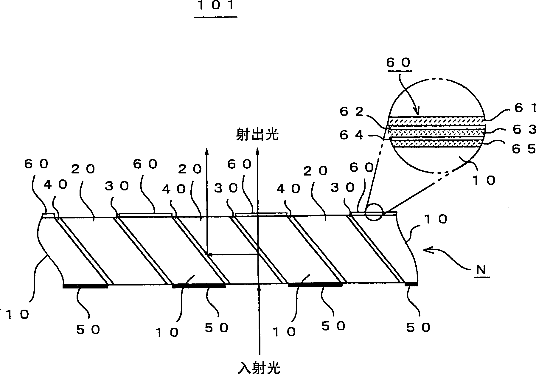
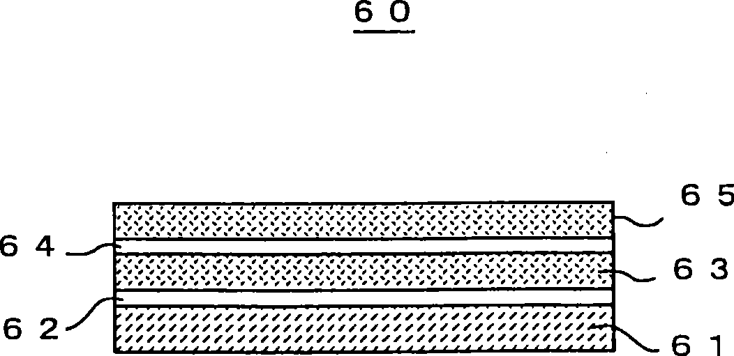
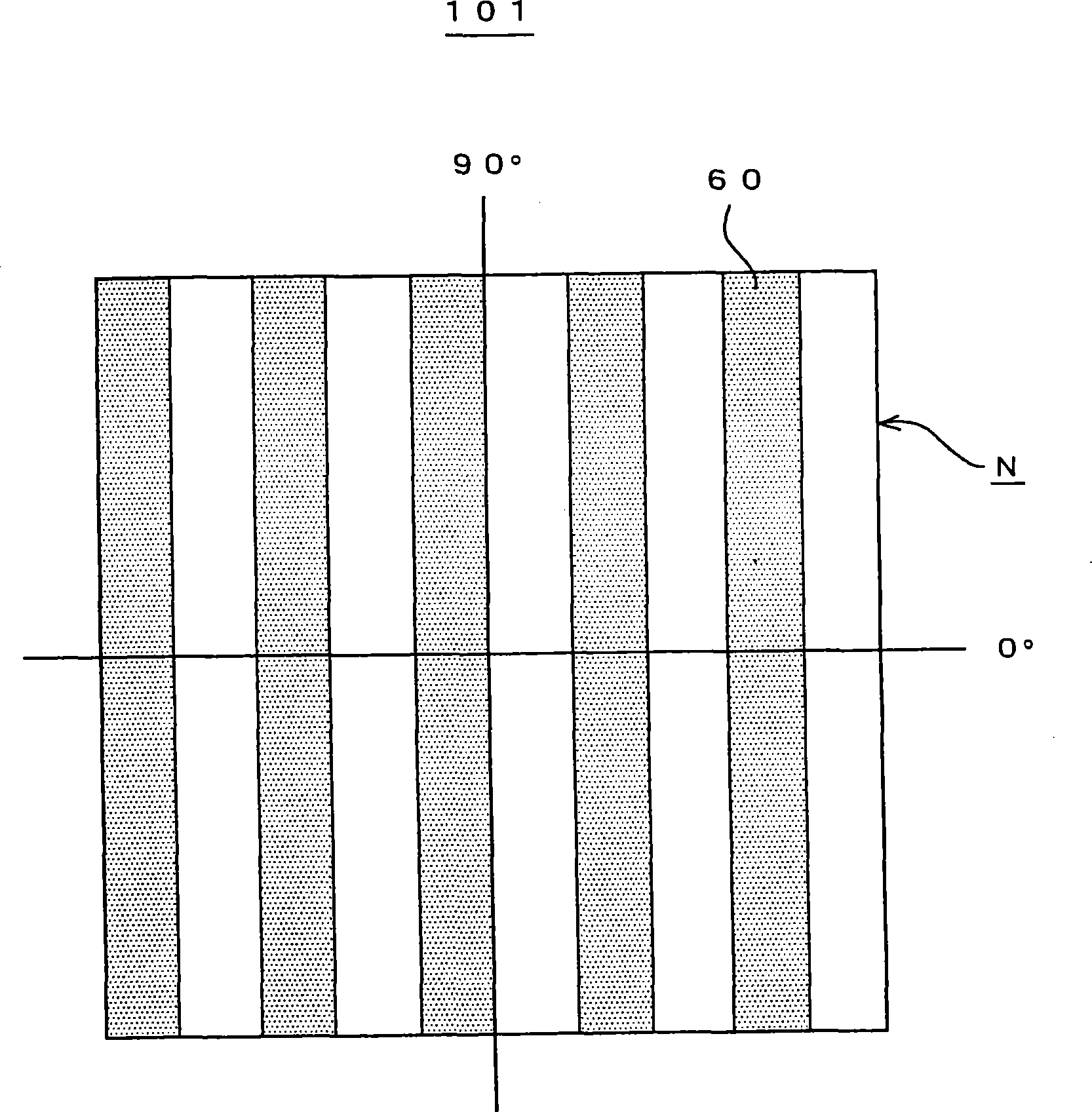
[0068] figure 1 It is a figure which shows the structure of the polarizing beam splitter 101 which is 1st Embodiment. in the figure 1 , a cross-sectional view of the polarizing beam splitter 101 is shown. figure 1 The enlarged part in represents a part of the cross section of the retardation film 60 . figure 2 It is a figure which shows the structure of the retardation film 60 of this invention.
[0069] Such as figure 1 As shown, the polarizing beam splitter 101 is composed of a first prism member 10 , a second prism member 20 , a polarization separation film (PBS film) 30 , a cold mirror 40 , a light shielding plate 50 , and a retardation film 60 .
[0070] In addition, the configuration of the polarizing beam splitter 101 is not limited to the configuration using the visor 50 . Other light shielding members may also be used.
[0071] The cross sections of the first prism member 10 and the second prism member 20 are formed in a parallelogram. In the case of a pol...
Embodiment 2
[0104] Figure 7 It is a figure which shows the structure of the polarizing beam splitter 102 which is 2nd Embodiment. in the Figure 7 A cross-sectional view of the polarizing beam splitter 102 is shown in .
[0105] Such as Figure 7 As shown, the polarizing beam splitter 102 is composed of a first prism member 10 , a second prism member 20 , a polarization separation film 30 , a cold mirror 40 , a light shielding plate 50 , a retardation film 60A, and an oxygen blocking layer 70 . In the case of this example, the oxygen barrier layer 70 is arranged on the upper part of the retardation film 60A through the adhesive 80 .
[0106] The retardation film 60A has two layers of polymer materials having liquid crystallinity. For example, the first alignment film 62 formed on the glass substrate 61 , the first liquid crystal polymer material layer 63 stacked on the first alignment film 62 , the second liquid crystal polymer material layer stacked on the first liquid crystal polym...
Embodiment 3
[0113] Figure 10 It is a sectional view showing the configuration of the polarizing beam splitter 103 as the third embodiment. Figure 10 The enlarged view of the X portion in the figure shows a part of the cross section of the retardation film 60B.
[0114] Such as Figure 10 As shown, the polarizing beam splitter 103 is composed of a first prism member 10, a second prism member 20, a polarization separation film 30, a cold mirror 40, a light shielding plate 50, and a retardation film 6OB. In the case of this embodiment, the retardation film 60B is arranged on the first prism member side of the polarization separation film 30 (the upper surface of the polarization separation film 30 ). This retardation film 60B functions as a positive A plate.
[0115] The retardation film 60B is formed by the same formation method as that of the retardation film 60 of the first embodiment described above, or is formed directly on the upper surface of the polarization separation film 30 w...
PUM
| Property | Measurement | Unit |
|---|---|---|
| Delay value | aaaaa | aaaaa |
Abstract
Description
Claims
Application Information
 - R&D
- Intellectual Property
- Life Sciences
- Materials
- Tech Scout
- Unparalleled Data Quality
- Higher Quality Content
- 60% Fewer Hallucinations
Browse by: Latest US Patents, China's latest patents, Technical Efficacy Thesaurus, Application Domain, Technology Topic, Popular Technical Reports.
© 2025 PatSnap. All rights reserved.Legal|Privacy policy|Modern Slavery Act Transparency Statement|Sitemap|About US| Contact US: help@patsnap.com


