Solar energy linkage tracking method

A solar energy and solar energy conversion technology, which is applied in the field of solar energy tracking and utilization, can solve the problems of affecting the use efficiency, high utilization cost and high cost, and achieve the effects of increasing wind resistance, reducing investment cost and improving use efficiency.

Inactive Publication Date: 2009-08-26
张玉良
View PDF1 Cites 26 Cited by
  • Summary
  • Abstract
  • Description
  • Claims
  • Application Information

AI Technical Summary

Problems solved by technology

[0002] At present, solar heat collection and power generation technologies are developing rapidly, but the common problem of low energy flux density of solar energy is still high utilization cost
The core of the vacuum tube or flat plate collector is limited by the material and process, and the cost is relatively high; the raw material output and cost of crystalline silicon for solar photovoltaic power generation (solar cell) are difficult to break through, and the cost will not drop quickly; solar thermal power generation is expected to To achieve large-scale, but no matter the dish type or trough type reflection concentrator or the tower type plane reflection concentrator, the common idea is to enlarge the size of a single reflector and provide a separate tracking system. Solar energy with a very low flux density is always difficult to take advantage of the low-cost advantages of reflectors, and there is still a long way to go before the low-cost comprehensive use that the whole society is eager to solve the pressure on energy and the environment.
[0003] The changing law of solar energy in the morning and evening makes solar energy utilization devices always have a "cosine effect" that affects the efficiency of use. At present, there is no universally suitable low-cost solar tracking technology to solve such problems

Method used


Image

  • Solar energy linkage tracking method
  • Solar energy linkage tracking method
  • Solar energy linkage tracking method

Examples


Embodiment 1

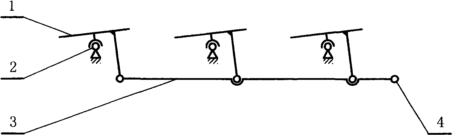
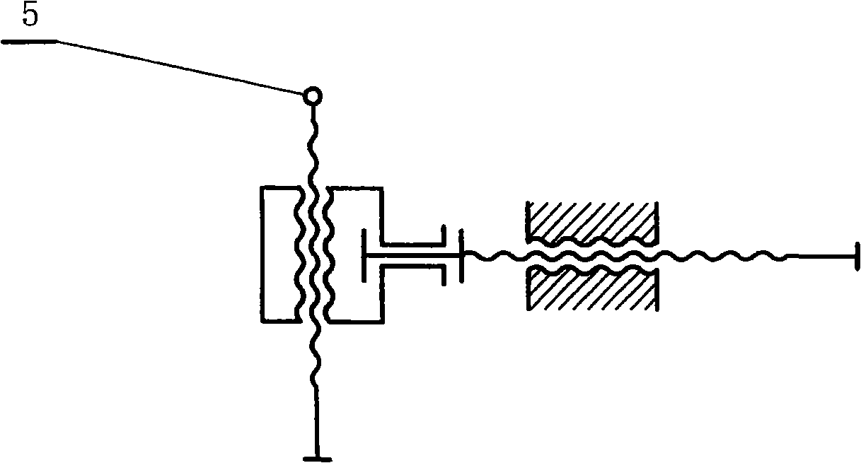
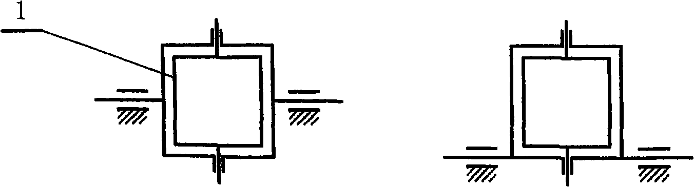
[0034] Embodiment 1: as attached figure 1 The solar conversion device 1 shown is a synchronous deflection mode supported by a single universal hinge (which can be deflected forward, backward, left, and right) and is connected by a connecting rod 3 to form a synchronous linkage mechanism of parallel connecting rods. The automatically controlled driving system is connected, and as the driving end 4 moves, all solar conversion devices will deflect synchronously. Because the tracking movement of the sun is divided into the daily tracking in the east-west direction and the annual tracking in the north-south direction, it is two-dimensional. figure 2 It means that the twin-screw mechanism can meet the two-dimensional movement of the displacement output end 5, and the two-dimensional movement of the output end 5 can meet the requirements of the design law by controlling the speeds of the two screws respectively by the control system. figure 1 When the driving input terminal 4 in th...

Embodiment 2

[0043] Embodiment 2: as attached Figure 8 Shown is a synchronous and interlocking plane concentrating schematic diagram of reflectors. The concentrating point is set in the concentrating plane formed by the sun rays passing through the deflection axis of the support frame. The support frame tracks the sun rays and deflects synchronously. Install with different deflection angles and phase differences in the deflection direction in the light-gathering plane to meet the need for a suitable deflection speed in the process of synchronous deflection tracking the sun so that the reflected light always faces the light-gathering point (receiver) in the light-gathering plane 11. In order to calculate the relationship between the "appropriate deflection speed" of the mirror surface and the deflection speed of the sun's rays in the light-gathering plane, the line a in the figure represents the sun's rays, b is the normal line of the mirror, c is the reflected light, d is the horizon, and...

Embodiment 3

[0057] Embodiment 3: as attached Figure 11 It is a schematic diagram of a synchronous interlocking plane concentrating system with downward secondary reflection. The high-position reflector 12 is added to first reflect the light to the plane mirror and then downward secondary reflection to the receiver 11, making solar high-temperature heating more convenient. The position of the focal point of the secondary reflection can be determined by the principle of mirror imaging (it is always mirror-symmetrical to the primary focal point), but the distance of the downward reflection should not be too large or the high-position reflector needs a large area. In order to adapt to concentrating heating in more areas, a convex reflector can be used to extend the reflection distance downward, which requires reducing the single mirror area of ​​the ground reflector. For example, when the diameter of the light spot produced after condensing light is 1 meter, if the area of ​​the single mirro...


PUM


Abstract

The invention relates to a solar energy linkage tracking method, which belongs to the field of solar energy utilization. In order to achieve the low-cost tracking with the solar energy, the method adopts a proposal that a polar energy utilization device is supported by a deflectable support frame, the polar energy utilization device and the deflectable support frame are connected with each other through a driving mechanism so as to form a linkage mechanism, and a driving device drags the linkage mechanism to achieve deflection and sun tracking. The solar energy linkage tracking method is applicable to various solar utilization projects to solve the effluence caused by cosine effect, can achieve planar light condensation of a solar energy reflector, can achieve the light convergence of a space heliostat by increasing compensating measures in the linkage mechanism, and provide a good solution for the solar energy low-cost heating power utilization and power generation.

Description

technical field [0001] The invention belongs to the field of solar tracking utilization. Background technique [0002] At present, solar heat collection and power generation technologies are developing rapidly, but the common problem of low energy flux density of solar energy is still high utilization cost. The core of the vacuum tube or flat plate collector is limited by the material and process, and the cost is relatively high; the raw material output and cost of crystalline silicon for solar photovoltaic power generation (solar cell) are difficult to break through, and the cost will not drop quickly; solar thermal power generation is expected to To achieve large-scale, but no matter the dish type or trough type reflection concentrator or the tower type plane reflection concentrator, the common idea is to enlarge the size of a single reflector and provide a separate tracking system. Solar energy with a very low flux density is always difficult to take advantage of the low...

Claims


Application Information

Patent Timeline
Patent Type & Authority Applications(China)
IPC IPC(8): G05D3/00F24J2/38H01L31/042H02N6/00G02B19/00G02B5/10G02B7/182F24S50/20H02S20/32
CPCY02E10/52Y02E10/47Y02E10/50
Inventor 张玉良
Owner 张玉良
Why Eureka
Try Eureka