
CO2 capture using solar thermal energy

A solar energy, CO2 technology, applied in the direction of solar thermal energy, solar thermal collectors using working fluid, solar thermal devices, etc., can solve problems such as reduced thermal efficiency

Inactive Publication Date: 2009-08-26
COMMONWEALTH SCI & IND RES ORG
View PDF0 Cites 15 Cited by
  • Summary
  • Abstract
  • Description
  • Claims
  • Application Information

AI Technical Summary

Problems solved by technology

[0009] In at least one or more aspects, it is an object of the present invention to more efficiently use solar energy to address the 2 The thermal efficiency reduction problem caused by post-combustion capture

Method used


Image

  • CO2 capture using solar thermal energy
  • CO2 capture using solar thermal energy
  • CO2 capture using solar thermal energy

Examples


Embodiment Construction

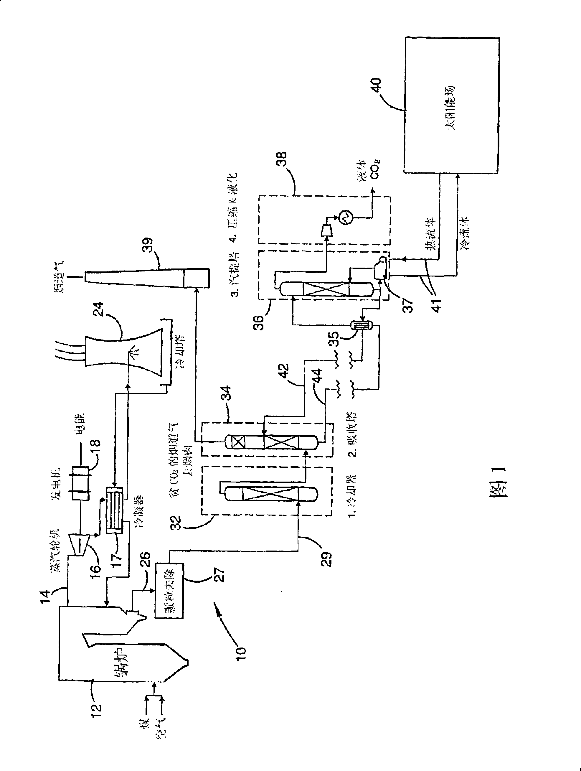
[0059] figure 1 The basic architecture of a coal fired power plant 10 is shown. The coal and air are sent to a large scale boiler system 12 which heats large volumes of water to generate steam 14 for driving a steam turbine 16 . However, the turbine 16 powers a generator 18 which produces electrical energy as its output. Steam recovered from the turbine 16 is circulated back to the boiler through a condenser 17 connected to a cooling tower 24 .

[0060] The flue gas 26 from the boiler 12 is treated (at 27) to remove most of the particulates and such as SO 2 and SO 3 Other impurities such as , are then passed at 29 to a four-stage plant for post-combustion capture of carbon dioxide. At stage 1 (indicated at 32), the cleaned flue gas is cooled to a suitable solvent system for efficient absorption of CO from the gas 2 temperature. These solvents are also sometimes called adsorbents. At stage 2 (including absorption stage 34), the cleaned and cooled flue gas is purified by ...


PUM


Abstract

At an absorber station, CO2 is absorbed from a gas stream into a suitable solvent whereby to convert the solvent into a CO2-enriched medium, which is conveyed to a desorber station, typically nearer to a solar energy field than to the absorber station. Working fluid, heated in the solar energy field by insolation, is employed to effect desorption of CO2 from the CO2-enriched medium, whereby to produce separate CO2 and regenerated solvent streams. The regenerated solvent stream is recycled to the absorber station. The CO2-enriched medium and / or the regenerated solvent stream may be selectively accumulated so as to respectively optimise the timing and rate of absorption and desorption of CO2 and / or to provide a storage of solar energy.

Description

technical field [0001] The present invention generally relates to the use of solar energy in the recovery of carbon dioxide from gas streams. The invention can be used in particular to recover CO from flue gases produced by coal or gas fired power plants or from process gases of numerous industrial processes including steel mills, furnaces, cement kilns and calciners 2 . The term "process gas" refers to a gas stream fed to or from a process including, for example, synthesis gas feed to industrial furnaces and blast furnace gas in steelworks. Background technique [0002] For fixed CO 2 Emission sources such as power plants, by 1) capturing the CO formed in the process 2 , and 2) CO storage by various geological means 2 There is increasing pressure to gradually reduce greenhouse gas (GHG) emissions. Most use the CO 2 Injection into deep aquifers, coal seams, and host rocks in a supercritical or "liquefied" state, or deep into the ocean, or CO 2 Converts to solid minera...

Claims


Application Information

Patent Timeline
Patent Type & Authority Applications(China)
IPC IPC(8): B01D53/14F24J2/34B01D53/18C01B32/50F24S90/00
CPCB01D53/1425F24J2/04Y02E10/44Y02C10/04Y02E70/30Y02C10/06F28D20/003B01D2256/22B01D53/1475Y02E60/142F24S10/00Y02C20/40Y02E60/14Y02P10/122Y02P20/133B01D53/14B01D53/18Y02P10/32
Inventor 路易斯·威伯利
Owner COMMONWEALTH SCI & IND RES ORG
Learn More