Full optical fiber current transformer adopting double closed loop control

A double-closed-loop control and current transformer technology, applied in the direction of inductors, voltage/current isolation, circuits, etc., can solve problems such as inability to guarantee the stability of transformers, slow drift of modulator performance, unfavorable long-term stability of optical paths, etc., to achieve improved Accuracy and stability, improve long-term stability, reduce the effect of optical path complexity

Active Publication Date: 2009-09-02
BEIJING AEROSPACE TIMES OPTICAL ELECTRONICS TECH
View PDF0 Cites 33 Cited by
  • Summary
  • Abstract
  • Description
  • Claims
  • Application Information

AI Technical Summary

Problems solved by technology

Among them, the light wave propagating in the glass block of the current transformer with magneto-optic glass structure is deflected under the action of the magnetic field, and the applied magnetic field strength can be obtained by detecting the deflection angle, so as to obtain the magnitude of the passing current. This scheme is an open-loop scheme , so there are shortcomings such as small measurement range, low sensitivity, and poor long-term stability; the other structure is an all-fiber structure, and a phase difference proportional to the magnetic field will be generated between the two beams of light waves propagating in the sensitive fiber. This phase difference can be detected, so as to obtain the current corresponding to the ma

Method used


Image

  • Full optical fiber current transformer adopting double closed loop control
  • Full optical fiber current transformer adopting double closed loop control
  • Full optical fiber current transformer adopting double closed loop control

Examples


Embodiment Construction

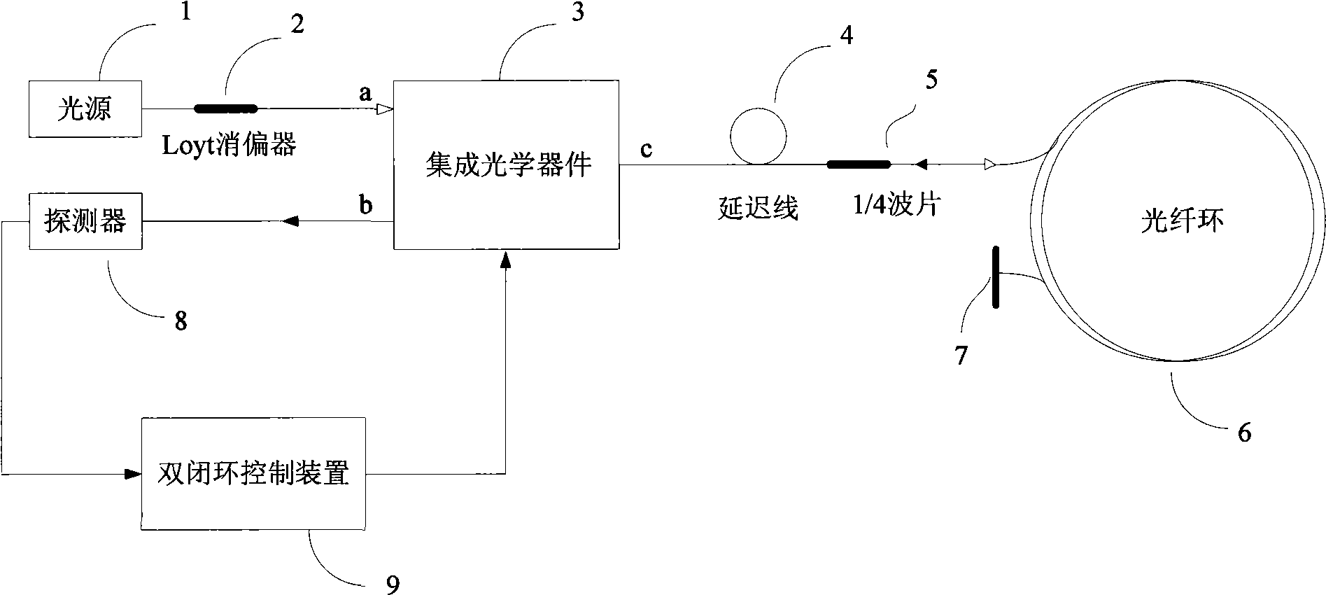
[0018] The essence of the optical fiber current transformer of the present invention is to use the interference principle of two beams of light to obtain the measured current by measuring the change of the interference light intensity. The proposed double closed-loop control not only completes the zero phase position caused by the current, but also accurately controls the reset of the modulated wave.

[0019] Such as figure 1 Shown is a block diagram of the structure and principle of the fiber optic current transformer of the present invention. The optical path includes a light source 1, a Loyt depolarizer 2, an integrated optical device 3, a polarization-maintaining fiber delay line 4, a λ / 4 wave plate 5, a sensitive fiber 6, a mirror 7, a photodetector 8 and a double closed-loop control device 9. The pigtail of the light source 1 is connected to the Loyt depolarizer 2, the other end of the Loyt depolarizer 2 is connected to the a-end of the integrated optical device 3, the ...


PUM


Abstract

The invention relates to a full optical fiber current transformer. After passing through a Loyt depolarization device, a light beam emitted by a light source enters an integrated optical device and produces two beams of linearly polarized light through the processing of the integrated optical device; and after passing through a polarization maintaining optical fiber delay line and a lambada/4 wave plate, the two beams of the linearly polarized light are converted into two beams of elliptically polarized light and enter sensitive optical fibers for transmission. Due to the Faraday magnetic optical effect, the two beams of the elliptically polarized light produce a phase difference under the action of a magnetic field produced by a tested current; subsequently the two beams of the light enter the sensitive optical fibers again after being reflected by a reflector; and the two beams of the light interchange the light paths and produce the phase difference again under the action of the magnetic field produced by the tested current. The two beams of the elliptically polarized light carrying current information return to the integrated optical device via the lambada/4 wave plate and the polarization maintaining optical fiber delay line to form interference light which is sent to a photo detector. The photo detector converts a light intensity signal carrying the information of the tested current into a voltage signal which is sent to a double closed loop control device. The double closed loop control device respectively completes the phase zero setting closed loop control and the modulated wave resetting closed loop control of the two beams of the linearly polarized light according to the voltage signal.

Description

technical field [0001] The invention relates to a current transformer, in particular to an all-optical fiber current transformer device which adopts double closed loops to control the phase difference of light waves and the reset error of modulated waves. Background technique [0002] Current transformer (abbreviated as CT) is an important equipment for relay protection and electric energy measurement in power system. Its long-term stability, reliability and safety are closely related to the safe and stable operation of power system. [0003] At present, the commonly used current transformers are mainly electromagnetic current transformers, which use the principle of electromagnetic induction to convert the current from the high-voltage side to the low-voltage side, so there are some difficulties that cannot be overcome in principle, such as ferromagnetic resonance, magnetic saturation, frequency band Limited, need to fill oil and gas, secondary open circuit hidden dangers a...

Claims


Application Information

Patent Timeline
IPC IPC(8): H01F38/28G01R15/18G01R15/24
Inventor 王巍张志鑫李永兵刘东伟阚宝玺杨清生王学锋杨仪松
Owner BEIJING AEROSPACE TIMES OPTICAL ELECTRONICS TECH
Why Eureka
Try Eureka