Energy-saving device and operation process for absorption-stabilization system

An absorption stabilization system and energy-saving device technology, applied in the petroleum industry, cracking, non-catalytic thermal cracking, etc., can solve the problems of increasing the energy consumption of the absorption stabilization system, increasing the energy consumption of the device, high absorption rate and desorption rate, etc., to achieve Significant energy-saving effect and economic benefits, increased yield, and reduced lean gas yield

Inactive Publication Date: 2009-09-16
TIANJIN UNIV
View PDF0 Cites 23 Cited by
  • Summary
  • Abstract
  • Description
  • Claims
  • Application Information

AI Technical Summary

Problems solved by technology

The single-tower process mainly has the following disadvantages: the absorption and desorption processes are carried out in the same tower, and the mutual interference is large; it is difficult to achieve a high absorption rate and desorption rate; it is difficult to control and adjust the device
[0006] The double-tower process overcomes the shortcomings of the single-tower process to a certain extent, but its process generally has the following problems: (1) The desorption tower is excessively desorbed, resulting in a large amount of C between the absorption tower and the desorption tower. 3 、C 4 Component recycling increases the energy consumption of the absorption stabilization system
(2) The absorption effect of the absorption tower is not ideal, and the lean gas contains a large amount of liquefied gas and stable gasoline, and the components of liquefied gas and stable gasoline circulate in the fractionation system and the absorption stabilization system, which further increases the energy consumption of the device
(3) The absorption effect of the reabsorption tower is not satisfactory, the content of C3 and C4 in the dry gas exceeds the standard, the yield of liquefied gas and stable gasoline decreases, and the economic benefits of the device are reduced

Method used


Image

  • Energy-saving device and operation process for absorption-stabilization system
  • Energy-saving device and operation process for absorption-stabilization system
  • Energy-saving device and operation process for absorption-stabilization system

Examples


Embodiment Construction

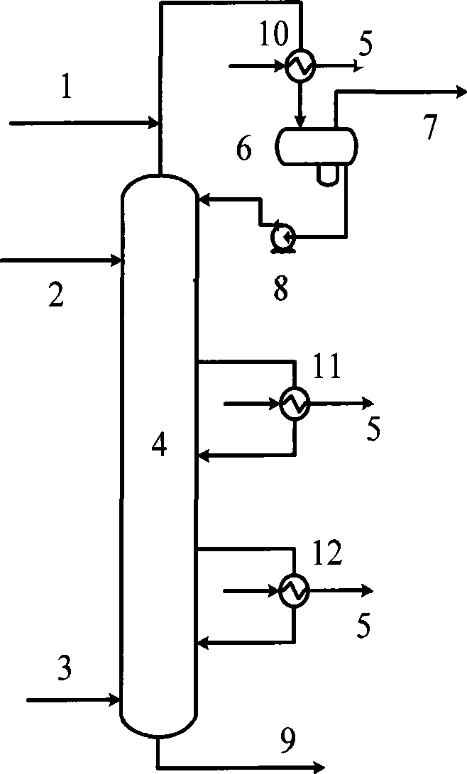
[0015] Below in conjunction with accompanying drawing, the present invention is described in further detail:

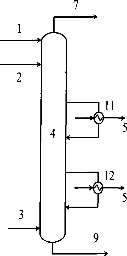
[0016] The process flow of the absorption stabilization system generally adopted in the comparison industry, such as figure 1 structure and connections shown.

[0017] Taking a refinery with a catalytic processing capacity of 0.012Mt / a as an example to simulate, the flow rate of naphtha is 11000kg / h, the flow rate of compressed rich gas is 8000kg / h, and the flow rate of light diesel oil is 4000kg / h: naphtha absorbent (2 ) temperature is 40 DEG C, enters the absorption tower (4) top; Stabilized gasoline supplementary absorbent (1) temperature is 40 DEG C, enters the absorption tower (4) tower top; Absorption tower (4) tower top lean gas (7) enters again The absorption tower is further processed; the middle and lower part of the absorption tower (4) is provided with two middle sections for heat extraction (11, 12) to take away the heat released during the absorption pr...


PUM


Abstract

The invention relates to an energy-saving device and an operation process for an absorption-stabilization system and a lean gas pre-balancing system is arranged at the top of an absorption tower. The lean gas pre-balancing system comprises a pre-balancing cooler, a pre-balancing tank and a pressurization pump; a supplementary absorbent and gas at the top of the absorption tower enter the pre-balancing tank after cooling for completing the pre-balancing operation, the gas phase of an outlet is lean gas, and the liquid phase is pressurized to be taken as the absorbent for the absorption tower. The invention has the advantages that the amount of the supplementary absorbent needed for stabilizing gasoline is reduced; heat loads of a desorption tower, a reboiler at the bottom of a stabilization tower and the like are reduced; loads of a liquefied gas condensing tank at the top of the stabilization tower, a gas-liquid separation tank after a compressor and the like are alleviated; the yieldof the lean gas is lowered, thereby being conductive to improving the yield of the liquefied gas and the gasoline and having significant energy-saving effect and economic benefits.

Description

technical field [0001] The invention relates to a petroleum refining process, in particular to an energy-saving device and an operating process for an absorption stabilization system. Background technique [0002] The absorption and stabilization system is a post-processing system for catalytic cracking and delayed coking devices. It separates raw naphtha and rich gas from the top of the main fractionation tower into product liquefied gas and stable gasoline, and at the same time obtains dry gas as a by-product. The product quality and energy consumption of the absorption stabilization system have a very important influence on the economic benefit of the whole processing unit. [0003] With the development of the economy, energy saving and product quality improvement have gradually become the most concerned issues in the oil refining industry. The old devices of the absorption stabilization system in the 1960s were all single-tower processes. The so-called single-tower proc...

Claims


Application Information

Patent Timeline
Patent Type & Authority Applications(China)
IPC IPC(8): C10G11/00C10G9/00
Inventor 隋红李国涛李鑫钢姜斌李洪
Owner TIANJIN UNIV
Why Eureka
Try Eureka