Water-spraying and exhaust-assisting energy-saving and emission-reduction method and device for internal combustion engine
A technology of energy saving and emission reduction, internal combustion engine, applied in the direction of internal combustion piston engine, combustion engine, charging system, etc., can solve the problems of not very ideal energy saving effect, narrow application range, complicated device structure, etc.
- Summary
- Abstract
- Description
- Claims
- Application Information
AI Technical Summary
Problems solved by technology
Method used
Image
Examples
Embodiment 1
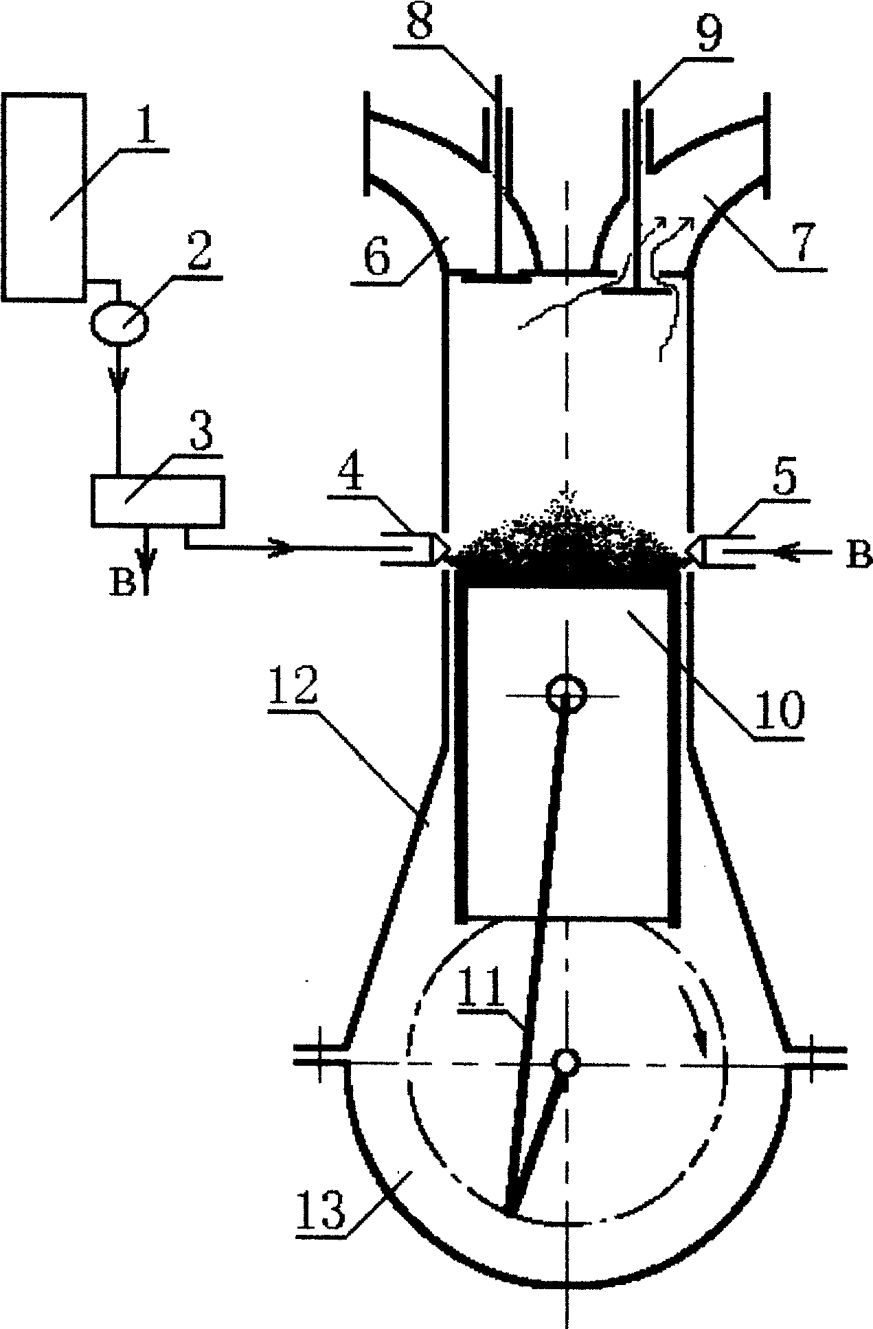
[0012] See attached figure 1 , mainly composed of water tank 1, water pump 2, pressure regulator 3, electric control nozzle 4, electric control nozzle 5, intake pipe 6, exhaust pipe 7, intake valve 8, exhaust valve 9, piston 10, connecting rod 11, Compositions such as fuselage 12, machine base 13 (due to four-stroke gasoline engine and diesel engine oil supply system are different, do not mark among the figure).
[0013] The water tank 1, the water pump 2, and the pressure regulator 3 generate stable water pressure. When the piston of the internal combustion engine runs to the exhaust stroke, through the electronically controlled nozzles 4 and 5, water is regularly sprayed to the top of the moving piston, and the water vapor evaporated by heat Helps expel exhaust gases from the combustion chamber. After the exhaust is completed, the water vapor left in the combustion chamber will be decomposed into hydrogen and oxygen under the action of high temperature and high pressure whe...
Embodiment 2
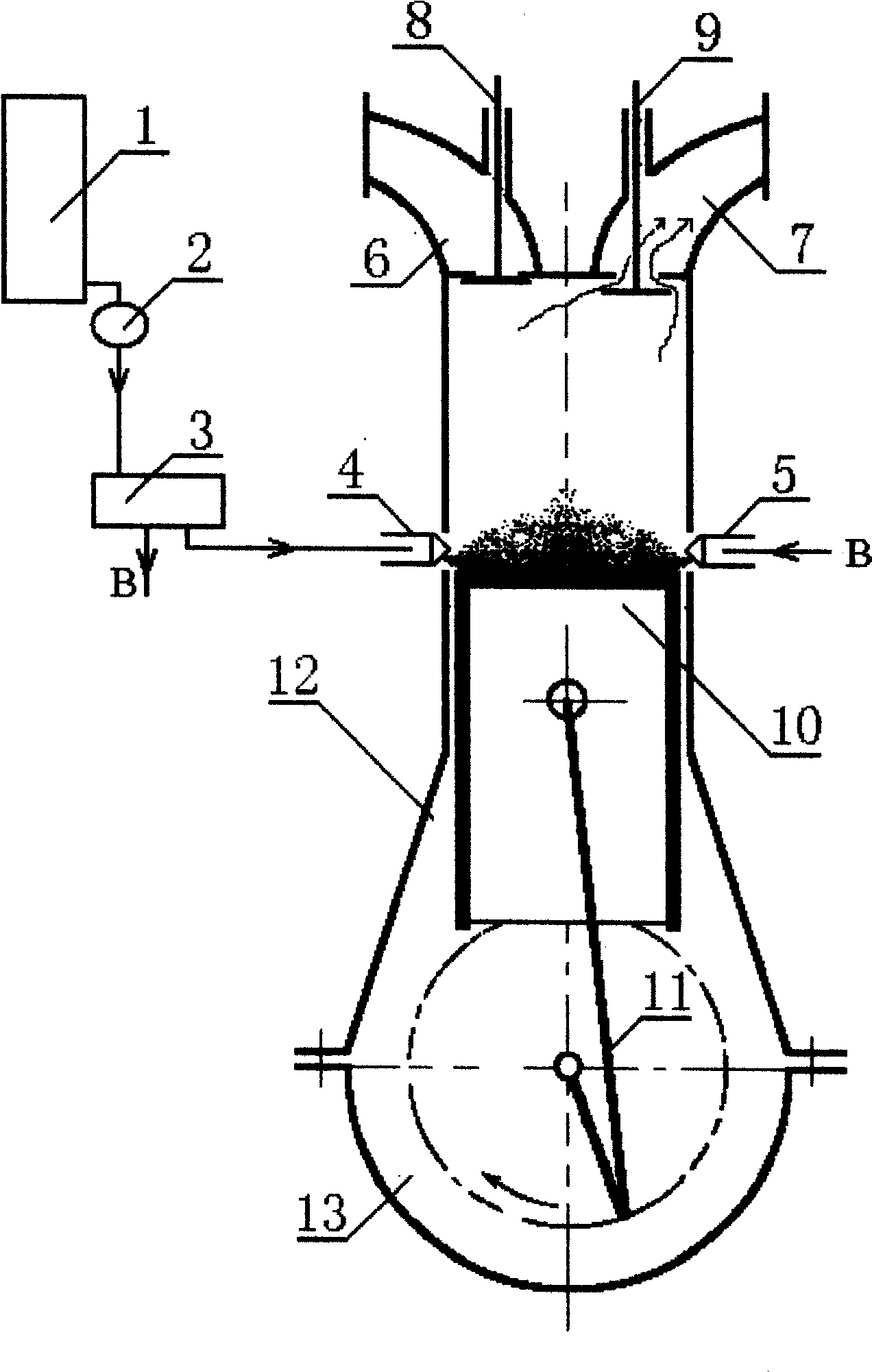
[0015] See attached figure 2 , mainly consists of water tank 1, water pump 2, high-pressure water pump 3, nozzle 4, nozzle 5, intake pipe 6, exhaust pipe 7, intake valve 8, exhaust valve 9, piston 10, connecting rod 11, body 12, machine Seat 13 etc. are formed (due to four-stroke gasoline engine and diesel engine oil supply system are different, do not mark among the figure).
[0016] The water tank 1 and the water pump 2 send water to the high-pressure water pump 3. After the expansion stroke of the internal combustion engine is almost finished and the exhaust valve is opened, the water pressure is rapidly increased through the high-pressure water pump 3. When the water pressure is greater than the spring force inside the nozzle 4 , the needle valve inside the nozzle 4 is jacked up, and the high-pressure water is sprayed out through the small hole on the nozzle (the same is true for the nozzle 5). Water is regularly sprayed to the top of the moving piston, and the heated an...
Embodiment 3
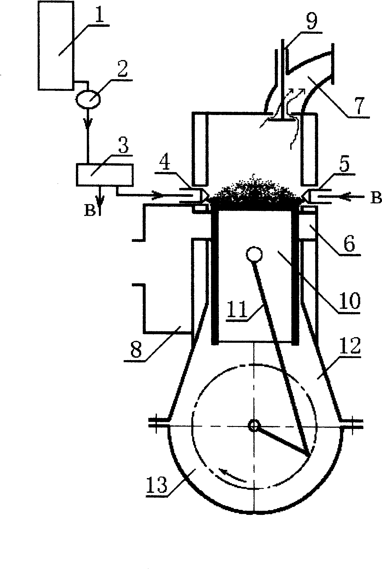
[0018] See attached image 3 , mainly composed of water tank 1, water pump 2, high-pressure water pump 3, nozzle 4, nozzle 5, scavenging air port 6, exhaust pipe 7, scavenging air box 8, exhaust valve 9, piston 10, connecting rod 11, body 12, machine Seat 13 etc. are formed (due to two-stroke gasoline engine and diesel engine oil supply system are different, do not mark among the figure).
[0019] The water tank 1 and the water pump 2 send water to the high-pressure water pump 3. The combustion expansion of the internal combustion engine and the exhaust scavenging stroke, when the exhaust valve is opened and before the scavenging port is opened, the water pressure is rapidly increased by the high-pressure water pump 3. When the water pressure was greater than the spring force inside the nozzle 4, the needle valve inside the nozzle 4 was lifted up, and the high-pressure water was ejected through the small hole on the nozzle (the same is true for the nozzle 5). Water is regular...
PUM
 Abstract
Description
Claims
Application Information
 - R&D
- Intellectual Property
- Life Sciences
- Materials
- Tech Scout
- Unparalleled Data Quality
- Higher Quality Content
- 60% Fewer Hallucinations
Browse by: Latest US Patents, China's latest patents, Technical Efficacy Thesaurus, Application Domain, Technology Topic, Popular Technical Reports.
© 2025 PatSnap. All rights reserved.Legal|Privacy policy|Modern Slavery Act Transparency Statement|Sitemap|About US| Contact US: help@patsnap.com


