Control apparatus for internal combustion engine

a control apparatus and internal combustion engine technology, applied in the direction of electric control, ignition automatic control, machines/engines, etc., can solve the problems of inability to maintain the combustion condition of diesel, the remaining fuel self-igniting with a rise in temperature and pressure in the combustion chamber, and the possibility of increasing the amount of smoke generated, so as to achieve the effect of improving the combustion condition and high self-ignition temperatur

Active Publication Date: 2017-08-29
TOYOTA JIDOSHA KK
View PDF5 Cites 8 Cited by
  • Summary
  • Abstract
  • Description
  • Claims
  • Application Information

AI Technical Summary

Benefits of technology

[0033]The present invention can improve the combustion condition in an internal combustion engine equipped with a super charger and performing diesel combustion using fuel having a relatively high self-ignition temperature, such as gasoline in an operation state in which the engine load is increased or decreased.
[0034]Further features of the present invention will become apparent from the following description of exemplary embodiments with reference to the attached drawings.

Problems solved by technology

Moreover, the remaining fuel self-ignites with a rise in the temperature and pressure in the combustion chamber resulting from the burning.
If the air-fuel ratio of air-fuel mixture deviates from a desired range due to such a response delay in changing the boost pressure, there may arise a possibility of increase in the amount of smoke generated and a possibility of instable diesel combustion.

Method used


Image

  • Control apparatus for internal combustion engine
  • Control apparatus for internal combustion engine
  • Control apparatus for internal combustion engine

Examples


example 1

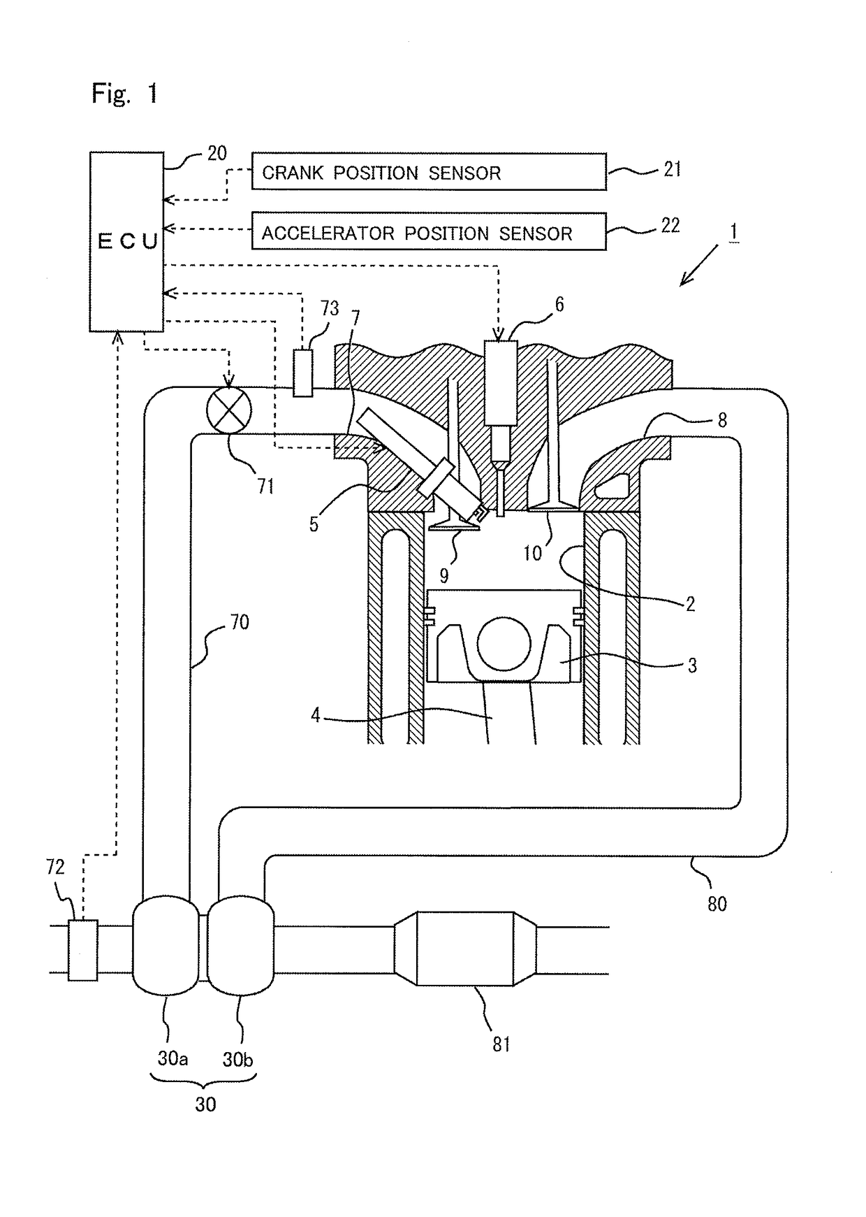
[0058]FIG. 1 is a diagram showing the general configuration of the air-intake and exhaust systems of an internal combustion engine to which the present invention is applied. The internal combustion engine 1 shown in FIG. 1 is a four-stroke-cycle, spark-ignition internal combustion engine (gasoline engine) having a plurality of cylinders. FIG. 1 shows only one of the plurality of cylinders.

[0059]In each cylinder 2 of the internal combustion engine 1, a piston 3 is provided in a slidable manner. The piston 3 is linked with an output shaft (crankshaft), which is not shown in the drawings, by a connecting rod 4. The interior of the cylinder 2 is in communication with intake ports 7 and exhaust ports 8. An end of the intake port 7 opening into the cylinder 2 is opened / closed by an intake valve 9. An end of the exhaust port 8 opening into the cylinder 2 is opened / closed by an exhaust valve 10. The intake valve 9 and the exhaust valve 10 are driven to be opened / closed respectively by an in...

example 2

[0154]In this example, operation ranges equivalent to the low load range R3, the middle load range R4, and the high load range R5 shown in FIGS. 15A and 15B will be referred to as low load range R3, first middle load range R4, and second middle load range R5. In this example also, the basic combustion control and the transient operation control same as those in example 1 are performed in the low load range R3, the first middle load range R4, and the second middle load range R5. In this example, the operation range in which the engine load is higher than the second middle load range will be referred to as high load range, in which high load combustion control is performed. In the following, the high load combustion control according to this example will be described.

[High Load Combustion Control]

[0155]In the internal combustion engine 1, when the engine load increases, it is necessary to increase the quantity of fuel injected into the combustion chamber. However, as described above, ...


PUM


Abstract

An object is to improve the combustion condition in an internal combustion engine equipped with a supercharger and performing diesel combustion using fuel having a relatively high self-ignition temperature in an operation state in which the engine load is increased or decreased. A control apparatus performs first injection during the compression stroke, causes spray guide combustion to occur, and starts to perform second injection at such a second injection time that combustion of injected fuel is started by flame generated by the spray guide combustion, thereby causing self-ignition and diffusion combustion of fuel to occur. During a response delay period in changing the boost pressure when changing the engine load of the internal combustion engine to a target engine load, the ratio of the quantity of fuel injected by the first injection to the total fuel injection quantity in one combustion cycle is made higher than the ratio of the quantity of fuel injected in the first injection to the total fuel injection quantity in one combustion cycle during the time when the engine load is equal to the target engine load and the actual boost pressure is equal to a target boost pressure corresponding to the target engine load.

Description

TECHNICAL FIELD[0001]The present invention relates to a control apparatus for an internal combustion engine equipped with a supercharger.BACKGROUND ART[0002]What is called diesel combustion, in which fuel is directly injected into compressed air in the combustion chamber, self-ignites, and is burned by diffusion combustion, has a higher thermal efficiency as compared to combustion by spark ignition. In recent years, in order to enjoy this advantage of diesel combustion also in gasoline engines, technology for causing gasoline to self-ignite and burn by diffusion combustion has been developed.[0003]For example, in the technology disclosed in PTL 1, a first fuel injection is performed by a fuel injection valve in a cylinder during the first half of the compression stroke to form substantially homogeneous air-fuel mixture in the entirety of the combustion chamber. Then, the air-fuel mixture formed by the first fuel injection is spark-ignited. Thereafter, a second fuel injection is perf...

Claims


Application Information

Patent Timeline
Patent Type & Authority Patents(United States)
IPC IPC(8): F02D41/40F02D41/30F02B23/10F02P5/15F02D41/00F02D41/10F02D41/12F02B75/12
CPCF02D41/403F02B23/101F02D41/0007F02D41/3017F02D41/3023F02D41/402F02P5/1504F02B2023/102F02B2023/103F02B2075/125F02D41/10F02D41/12F02D41/3041F02D41/401F02D41/405F02D2200/0406Y02T10/123Y02T10/125Y02T10/144Y02T10/44Y02T10/46Y02T10/12Y02T10/40
Inventor OCHI, YUTAKASHIWAGURA, TOSHIMI
Owner TOYOTA JIDOSHA KK
Why Eureka
Try Eureka