Internal-combustion engine cooling system based on integrative permanent magnet synchronous motor water pump and electronic speed regulation technology

A technology of permanent magnet synchronous motor and electronic speed regulation, which is applied in the direction of engine cooling, machine/engine, and coolant flow control, etc. It can solve problems such as reduced reliability, high cost, and complex cooling system performance. The effect of stabilizing the temperature of the body and increasing the temperature of the body

Inactive Publication Date: 2010-05-19
SHANDONG UNIV OF SCI & TECH
View PDF0 Cites 9 Cited by
  • Summary
  • Abstract
  • Description
  • Claims
  • Application Information

AI Technical Summary

Problems solved by technology

Compared with the mechanical thermostat, the sensitivity of the electronic thermostat is slightly improved, but it does not substantially improve the performance of the cooling system, but makes the cooling system more complicated
The electric water pump and the electronically controlled cooling system will greatly improve the performance of the cooling system, but the electric water pump with the existing structure adopts the structure of the ordinary electric water pump in order to ensure the performance of the motor. Transmission, there are dynamic sealing parts on the shaft, so not only the cost is high but also the reliability is reduced. At present, it is only reported to be applied to a high-end engine of BMW (it is also reported that other new models that will be put into production in the next few years, such as Toyota, will also be used. Cooling system with electric water pump)

Method used


Image

  • Internal-combustion engine cooling system based on integrative permanent magnet synchronous motor water pump and electronic speed regulation technology
  • Internal-combustion engine cooling system based on integrative permanent magnet synchronous motor water pump and electronic speed regulation technology
  • Internal-combustion engine cooling system based on integrative permanent magnet synchronous motor water pump and electronic speed regulation technology

Examples


Embodiment Construction

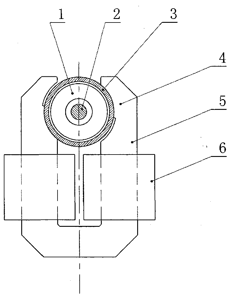
[0051] The specific implementation manner of the present invention will be described below in conjunction with the accompanying drawings.

[0052] Depend on figure 1 It can be seen that the structure of the integrated permanent magnet synchronous motor water pump is as follows. 1. The permanent magnet rotor (1) generally adopts an integral two-pole magnetized permanent magnet. The permanent magnet can be ferrite, neodymium iron boron, etc. through sintering, Manufactured by bonding or injection molding, the permanent magnet rotor (1) is equipped with a shaft (2), and the water pump impeller can be directly installed on the shaft (2) to form a coaxial structure of coaxial connection and coaxial rotation. Compared with the coaxial structure that is connected around the coaxial rotation, the advantage is that a cover plate that doubles as a bearing and prevents impurities in the coolant from entering can be installed between the permanent magnet rotor (2) and the impeller. This c...


PUM


Abstract

The invention discloses an internal-combustion engine cooling system based on an integrative permanent magnet synchronous motor water pump and an electronic speed regulation technology, belonging to the (electronic control) technical field of internal-combustion engine. The internal-combustion engine cooling system can be used for small water-cooled internal-combustion engine cooling systems and can be used for cooling other mechanical, electronic and electrical equipment. The purpose of the invention is to bring simple system, improve cooling control performance and temperature control precision, lower power consumption and obviously improve reliability and practicality. The internal-combustion engine cooling system is characterized in that the internal-combustion engine cooling system comprises a single circulation path cooling circulation system; a permanent magnet rotor operating in a water pump case forms an integrative permanent magnet synchronous motor water pump; the permanent magnet synchronous motor water pump, a temperature sensor and an electronic speed regulation driving circuit form an automatic cooling control system which can realize required temperature-water pump flow characteristic and engine body temperature-heat dissipating characteristics and can keep the engine body temperature stable.

Description

technical field [0001] The invention relates to an internal combustion engine cooling system based on an integrated permanent magnet synchronous motor water pump and electronic speed regulation technology, which belongs to the technical field of (motor vehicle) internal combustion engine (electric control) or automatic control device, and can be used for cooling small water-cooled internal combustion engines The system can also be used for cooling systems of other mechanical, electronic or electrical equipment (or their components). Background technique [0002] The internal combustion engine cooling system is mainly divided into water cooling system or air cooling system. Small internal combustion engines such as motorcycle internal combustion engines also use an oil cooling system similar in principle to the water cooling system. With the advancement of technology and the improvement of environmental protection and energy saving standards, modern internal combustion engine...

Claims


Application Information

Patent Timeline
Patent Type & Authority Applications(China)
IPC IPC(8): F01P7/16F01P5/10F01P5/12
Inventor 于昊昱衣美凤于佳衣
Owner SHANDONG UNIV OF SCI & TECH
Why Eureka
Try Eureka