High-power planar transformer

A planar transformer and high-power technology, applied in the field of transformers, can solve problems such as complex structure and process, inability to pass large current, complexity, etc., and achieve the effect of simple manufacturing process, high degree of insulation, and reduced volume

Active Publication Date: 2011-05-25
铂恩氏(东莞)电子有限公司
View PDF0 Cites 0 Cited by
  • Summary
  • Abstract
  • Description
  • Claims
  • Application Information

AI Technical Summary

Problems solved by technology

Planar transformers with this structure often have the following problems: ①The insulation distance required by safety regulations is difficult to achieve, especially the reinforced insulation required by safety regulations in AC / DC converters, which is more complicated to implement and often requires a special framework to achieve the purpose ;②Due to the multi-layer superimposition, the structure and technology are complicated, and the processing and production are difficult
However, since the transformer winding itself is a part of the motherboard PCB, it must be limited by the number of PCB layers and copper thickness, and cannot pass a large current, so it can only be used in low-power applications.

Method used


Image

  • High-power planar transformer
  • High-power planar transformer
  • High-power planar transformer

Examples


Embodiment Construction

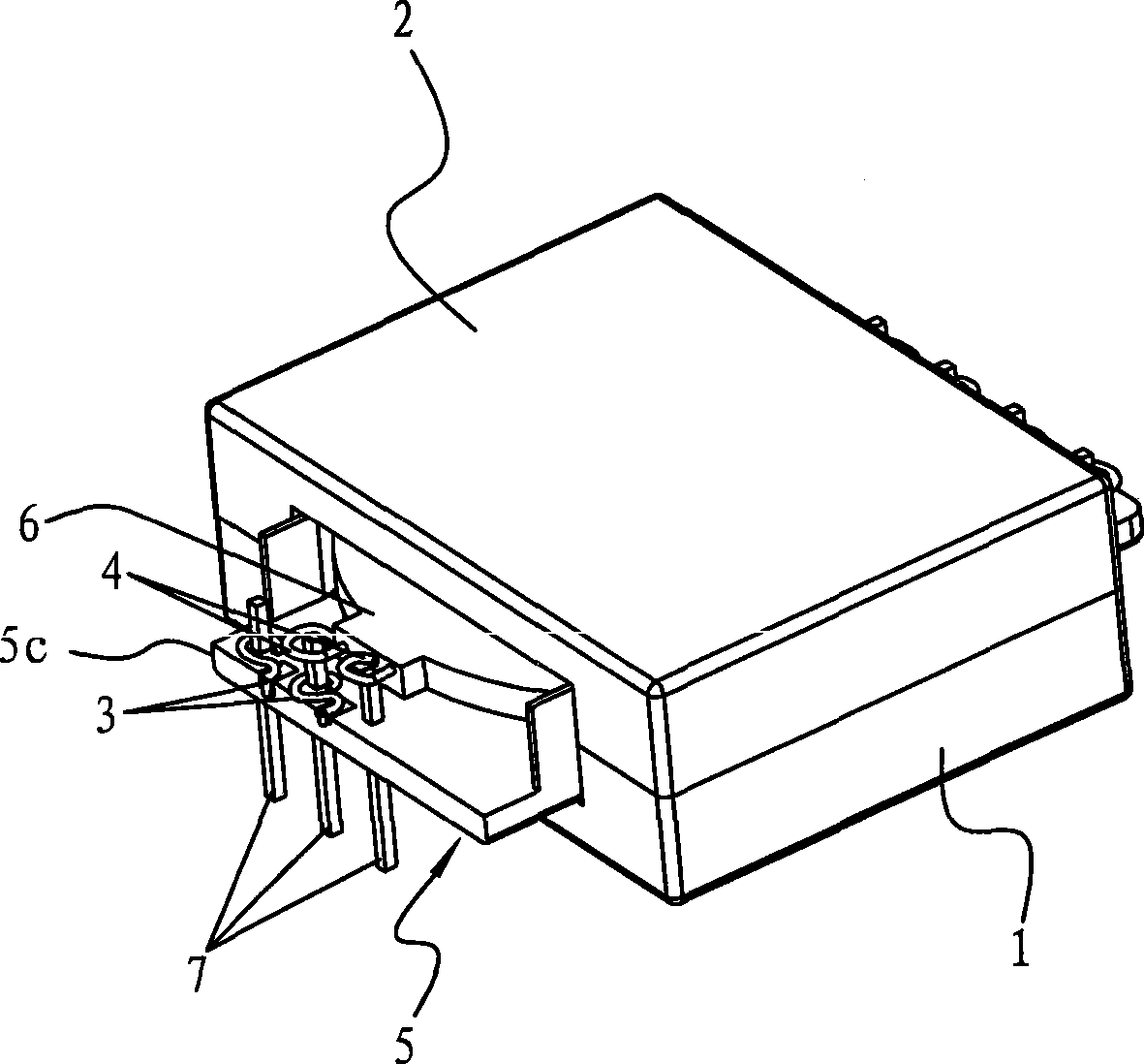
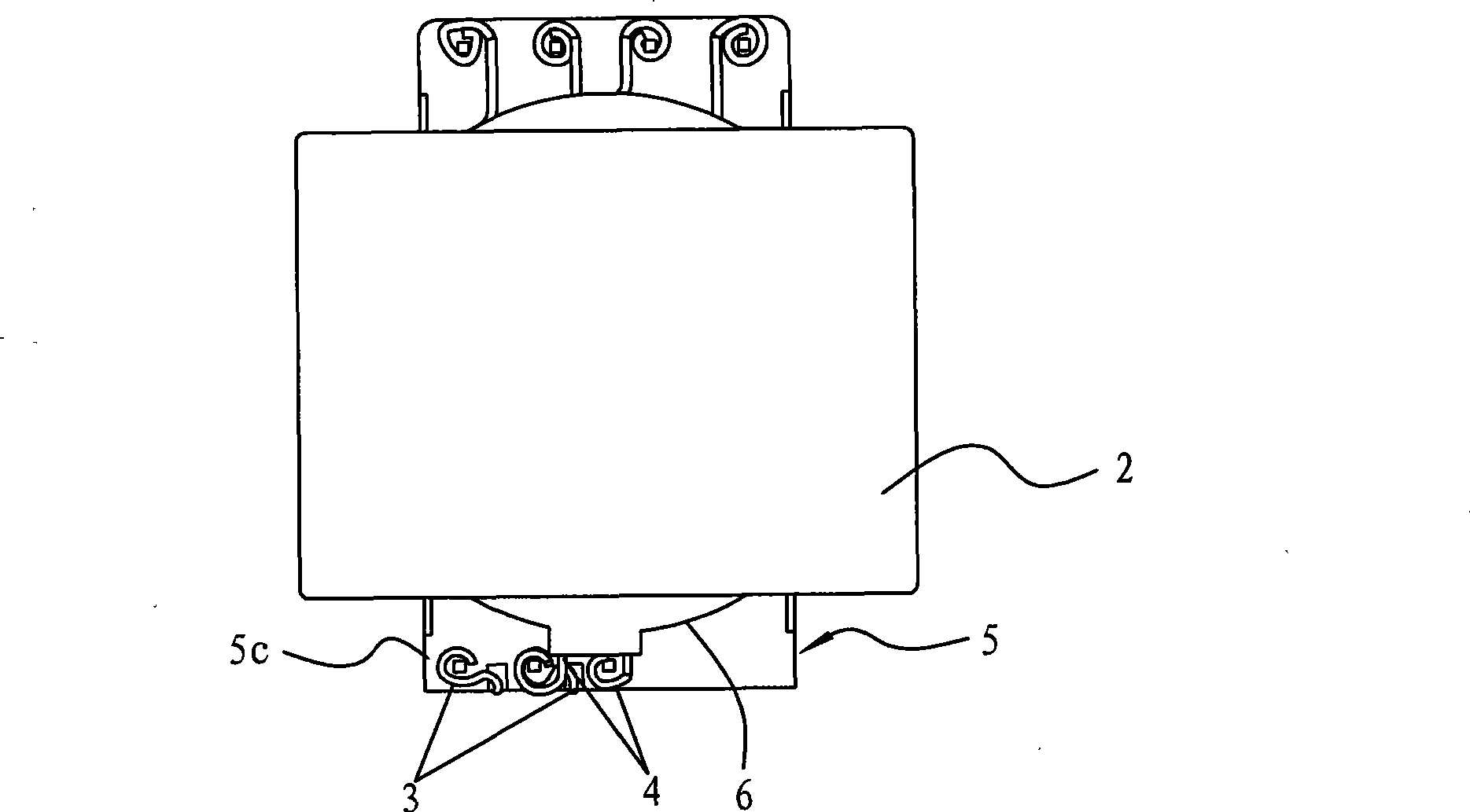
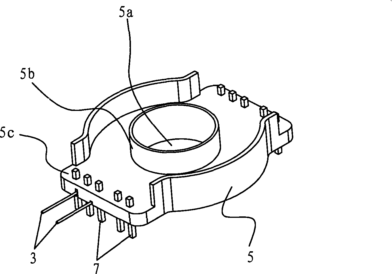
[0024] See Figures 1 to 4 , which is one of the embodiments of the present invention, including the first magnetic core 1, the second magnetic core 2, the primary coil 3, the secondary coil 4 and the insulating base 5, the primary coil 3 and the secondary coil 4 are self-adhesive coils ; The insulating base 5 is provided with a central axis hole 5a, and the edge of the central axis hole 5a of the insulating base 5 is provided with an annular bushing 5b, and the primary coil 3 is arranged inside the insulating base 5, forming an integral structure with the insulating base 5; The secondary coil 4 is arranged inside the rubber plate 6 and forms an integral structure with the rubber plate 6. The rubber plate 6 is provided with a through hole 6a, and the inner diameter of the through hole 6a is larger than the outer diameter of the shaft sleeve 5b. The rubber plate 6 The first magnetic core 1 and the second magnetic core 2 are placed on both sides of the insulating base 5 through ...


PUM


Abstract

The invention relates to the technical field of transformers, in particular to a high-power planar transformer, which comprises a first magnetic core, a second magnetic core, a primary coil, a secondary coil and an insulating base, wherein the primary coil and the secondary coil are self-adhesion coils; the insulating base is provided with a centre shaft hole, the primary coil is arranged inside the insulating base and forms an integral structure with the insulating base, and the secondary coil is stacked on the insulating base; the first magnetic core and the second magnetic core are placed at two sides of the insulating base and form a magnetic path through the centre shaft hole; and the primary coil and the secondary coil are coupled. Because the coils are separately arranged inside aninsulator, the insulating degree is high, the manufacturing technology of the coils is simple, and the coils can be molded integrally through mold pouring; and because the coils are arranged inside the insulator, the structure can be more compact, the volume of the transformer is reduced, and the high-power planar transformer can be applied to thinner electronic products.

Description

Technical field: [0001] The invention relates to the technical field of transformers, in particular to a high-power planar transformer. Background technique: [0002] As the requirements for the power density of switching power supplies are getting higher and higher, the requirements for transformers, which are one of the bottlenecks in volume and weight of switching power supplies, are bound to be higher and higher. The use of planar transformers to replace traditional skeleton transformers is one of the important development trends of current switching power supplies. [0003] Existing planar transformers (especially for high-current and high-power applications) mostly use copper skin as the primary / secondary winding, stack multiple such windings together, and then form a transformer together with the magnetic core. Planar transformers with this structure often have the following problems: ①The insulation distance required by safety regulations is difficult to achieve, es...

Claims


Application Information

Patent Timeline
Patent Type & Authority Patents(China)
IPC IPC(8): H01F27/28H01F27/32H01F41/12
Inventor 孔浩叶维
Owner 铂恩氏(东莞)电子有限公司
Why Eureka
Try Eureka