Separation membrane-porous material composite and method for manufacturing the same
A porous material and separation membrane technology, applied in separation methods, semi-permeable membrane separation, dispersed particle separation, etc., can solve problems such as low flow rate and poor selectivity
- Summary
- Abstract
- Description
- Claims
- Application Information
AI Technical Summary
Problems solved by technology
Method used
Image

Examples
example 1
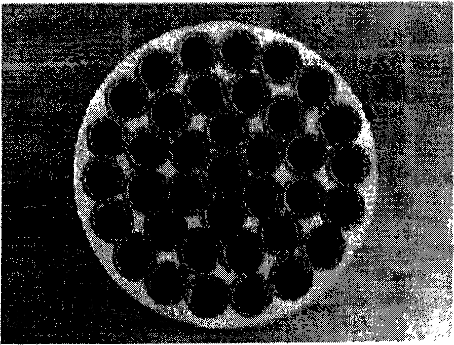
[0056] Although formed by extrusion and sintering, a substrate having a monolithic shape with an average particle diameter of 10 to 100 μm and an average pore diameter of 1 to 30 μm was prepared. Next, on the inner wall surface of the basal cell, aluminum microparticles having an average particle diameter of 0.3 to 10 μm are deposited by a filtration film forming method, followed by sintering to form a middle layer having a thickness of 10 to 1000 μm and an average pore size of 0.1 to 3 μm. Floor. On the intermediate layer, aluminum particles having an average particle diameter of 0.3 to 1 μm are further deposited by a filter film forming method, followed by sintering to form a dense layer having a thickness of 1 to 100 μm and an average pore diameter of 0.01 to 0.5 μm. A porous material is thus obtained.
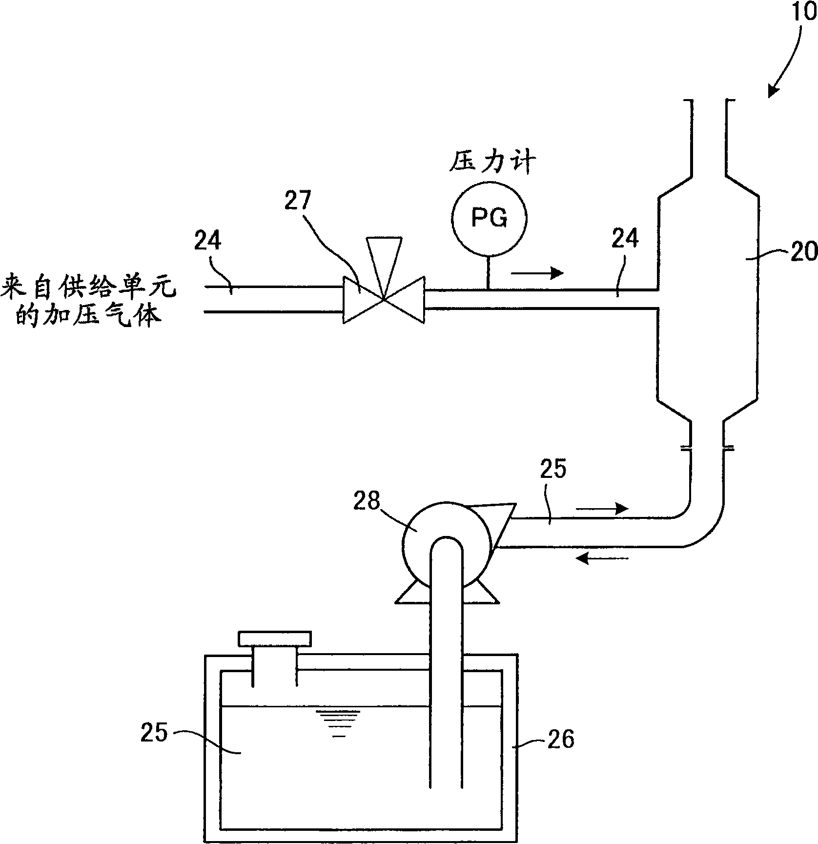
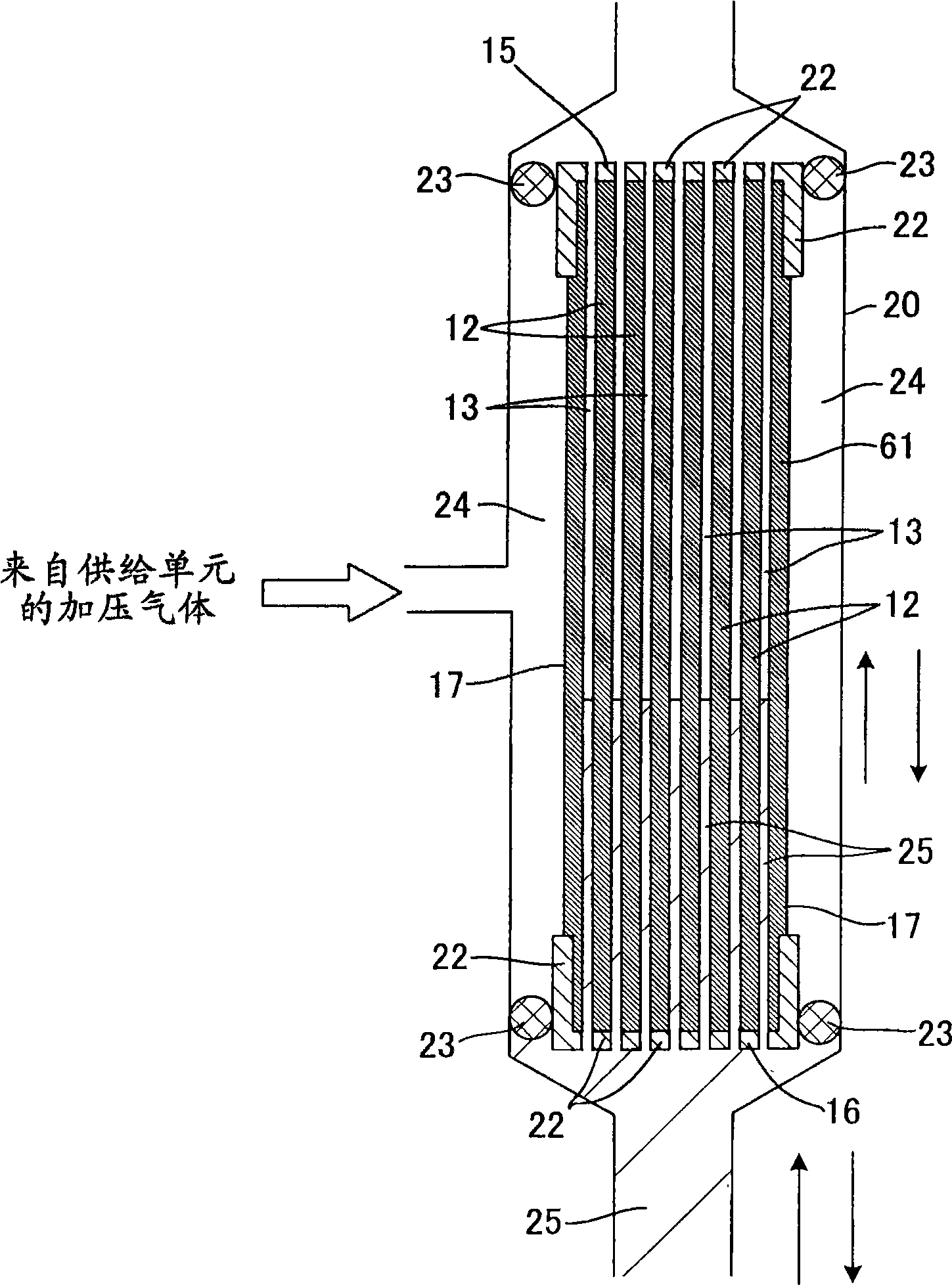
[0057] Next, use figure 1 with 2 In the device 10 shown in , helium gas with a pressure of 1 kPa is injected into the pores of the porous material, and through the insid...
example 2
[0060] A separation membrane-porous material composite was prepared in the same manner as in Example 1 except that the inside of the pores was pressurized with helium gas having a pressure of 50 kPa and injected into the pores of the porous material. The separation membrane-porous material composite was evaluated by the water-ethanol pervaporation method under the same conditions as in Example 1. Table 1 shows the precursor solution consumption and pervaporation performance (separation factor and flow rate) for forming carbon thin films.
example 3
[0062] A separation membrane-porous material composite was prepared in the same manner as in Example 1 except that the inside of the pores was pressurized with helium gas having a pressure of 100 kPa and injected into the pores of the porous material. The separation membrane-porous material composite was evaluated by the water-ethanol pervaporation method under the same conditions as in Example 1. Table 1 shows the precursor solution consumption and pervaporation performance (separation factor and flow rate) for forming carbon thin films.
PUM
| Property | Measurement | Unit |
|---|---|---|
| thickness | aaaaa | aaaaa |
| thickness | aaaaa | aaaaa |
| thickness | aaaaa | aaaaa |
Abstract
Description
Claims
Application Information
 - R&D
- Intellectual Property
- Life Sciences
- Materials
- Tech Scout
- Unparalleled Data Quality
- Higher Quality Content
- 60% Fewer Hallucinations
Browse by: Latest US Patents, China's latest patents, Technical Efficacy Thesaurus, Application Domain, Technology Topic, Popular Technical Reports.
© 2025 PatSnap. All rights reserved.Legal|Privacy policy|Modern Slavery Act Transparency Statement|Sitemap|About US| Contact US: help@patsnap.com