Amplifier

A technology of amplifiers and operational amplifiers, applied in differential amplifiers, DC-coupled DC amplifiers, improved amplifiers to reduce temperature/power supply voltage changes, etc., can solve problems such as affecting the use of equipment, burning speakers or earphones, and unpleasant audiences, etc., to achieve Good isolation, low power consumption and cost, good sound effects

Inactive Publication Date: 2009-09-23
ALLWINNER TECH CO LTD
View PDF0 Cites 23 Cited by
  • Summary
  • Abstract
  • Description
  • Claims
  • Application Information

AI Technical Summary

Problems solved by technology

[0009] When the operational amplifier 10 is turned on, that is, when the enable terminal EN of the operational amplifier 10 changes from a low level to a high level, the signal output terminal voltage of the operational amplifier 10 jumps from 0V to the reference voltage VREF very quickly (such as Figure 4 401 in ), and because the voltage difference across the DC blocking capacitor C1 cannot change suddenly, the voltage difference across the load will generate a positive spike with an amplitude as high as VREF (such as Figure 5 shown in 501), which is often referred to as boot impact noise, which will affect the user's experience and even affect the use of the device
For example, for audio processing equipment, the noise will appear as a loud "bang" from the speaker or earphones, causing unpleasant feelings to the audience, and may even burn the speakers or earphones
[0010] When the operational amplifier 10 is turned off, a similar situation also occurs, specifically, when the enable terminal EN of the operational amplifier 10 changes from a high level to a low level and the operational amplifier 10 is turned off, the signal output of the operational amplifier 10 The terminal voltage quickly jumps from the reference voltage VREF to 0V (such as Figure 4 402 in ), and since the voltage difference across the DC blocking capacitor C1 cannot change suddenly, the voltage difference across the load will generate a negative spike with an amplitude as high as VREF (such as Figure 5 shown in 502), which is often referred to as shutdown impact noise, which will also affect the user's experience and even affect the use of the device

Method used


Image

  • Amplifier
  • Amplifier
  • Amplifier

Examples


Embodiment 1

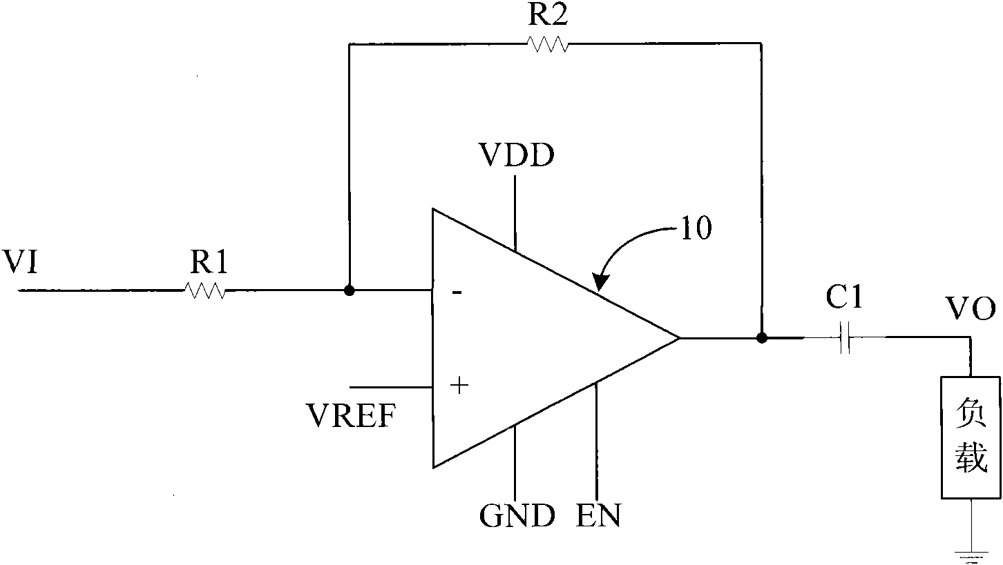
[0034] Figure 6The schematic diagram of the amplifier structure provided for this embodiment, as shown in the figure, the amplifier includes: an operational amplifier 10, a DC blocking capacitor C1, an input impedance circuit R1, a feedback impedance circuit R2, a ramp voltage generation circuit 72, and an enable signal delay control circuit 76 , Analog switch 74. Wherein, the signal output terminal OPO of the operational amplifier 10 is connected to one end of the DC blocking capacitor C1, the other end of the DC blocking capacitor C1 is connected to the input terminal of the load, and the feedback impedance circuit R2 is arranged between the negative signal input terminal of the operational amplifier 10 and the input terminal of the load. between the signal outputs.

[0035] Enable signal delay control circuit 76, its input end receives external enable signal, and the first output end is connected with the enable end of operational amplifier 10, is used for under the contr...

Embodiment 2

[0042] The structure of the amplifier of this embodiment is as Figure 6 As shown, the difference is that, specifically in this embodiment:

[0043] Enable signal delay control circuit 76 When the input external enable signal is effective, the first output terminal outputs an effective enable signal ENOP (see Figure 7 703 in ), to turn on the operational amplifier 10; after its first input end receives an effective external enable signal, its second output end delays the second time interval T2, and outputs an effective switch control signal MUTE (see Figure 7 702) to turn on the analog switch 74.

[0044] It can be seen that when the amplifier is turned on and the external enabling signal is valid, the enabling signal delay control circuit 76 outputs an effective enabling signal to the enabling terminal of the operational amplifier 10 to turn on the operational amplifier 10, and when the external enabling signal is valid , the slope voltage generating circuit 72 outputs a...

Embodiment 3

[0048] The structure of the amplifier of this embodiment is as Figure 6 As shown, the difference from Example 1 is, specifically in this example:

[0049] When the external enable signal is invalid, the second output end of the enable signal delay control circuit 76 outputs a switch control signal MUTE (see Figure 7 In 705), to disconnect the analog switch 74; the first output terminal of the enable signal delay control circuit 76 delays the fourth time interval T4 after the external enable signal fails, and prohibits the output enable signal (see Figure 7 In 706), to turn off the operational amplifier 10;.

[0050] The slope voltage generating circuit 72 outputs a second slope voltage signal (see Figure 7 704 ): the voltage starts to drop slowly from the reference voltage, reaches 0V after a predetermined third time interval T3, and then remains at 0V.

[0051] It can be seen that when the amplifier is turned off and the external enable signal is invalid, the second ou...


PUM


Abstract

The invention relates to the field of circuit design and discloses an amplifier. The amplifier is provided with a slope voltage generating circuit, an enabling signal delay controlling circuit and an analog switch inside to enable the amplifier to realize lower circuit power consumption and low cost and reduce the impact noise during switching on or switching off, wherein the slope voltage generating circuit outputs a slope voltage signal to an operating positive signal input terminal when the external enabling signal is available; the voltage starts to rise from 0 V and reaches a reference voltage after passing T1, and then is continuously stabilized on the reference voltage; the enabling signal delay controlling circuit carries out the following operation when the input external enabling signal is available: changing the enabling signal which is output and connected with an operating enabling terminal into the available enabling signal, starting to operate, changing a switch controlling signal which is output and connected with a controlling terminal of the analog switch into the available switch controlling signal after delaying T2, and conducting the analog switch; and the analog switch conducts or cuts off the connection of an input impedance circuit and the operation under the control of the switch controlling signal.

Description

technical field [0001] The invention relates to the field of circuit design, in particular to an amplifier. Background technique [0002] Amplifiers are generally used to amplify or attenuate analog signals, filter, impedance transform, power drive, etc. For example, audio power amplifiers are used to amplify audio signals and drive speakers to produce sound. The coupling of the amplifier to the post-stage circuit or load (for the convenience of description, hereinafter collectively referred to as the load) usually adopts the following two methods: [0003] First, the direct DC coupling method. Such as figure 1 As shown, the operational amplifier 10 amplifies the input signal VI to output the signal Vo, and then inputs the output signal Vo to the load. In order to prevent the load from flowing through a DC current, an operational amplifier with the same power as the operational amplifier 10 is externally connected to the other end of the load. Amplifier 12. [0004] Alth...

Claims


Application Information

Patent Timeline
Patent Type & Authority Applications(China)
IPC IPC(8): H03F1/30H03F3/45H03K4/02H03K19/173
Inventor 刑涛
Owner ALLWINNER TECH CO LTD
Why Eureka
Try Eureka