
Multi-slit convex grating imaging spectrograph

An imaging spectrometer and convex grating technology, applied in the field of systems and optical components, can solve problems such as lack of ground object image classification

Inactive Publication Date: 2009-09-30
SHANGHAI INST OF TECHNICAL PHYSICS - CHINESE ACAD OF SCI
View PDF0 Cites 21 Cited by
  • Summary
  • Abstract
  • Description
  • Claims
  • Application Information

AI Technical Summary

Problems solved by technology

However, the current technological level cannot achieve such a large-size focal plane device, so splicing of devices is generally used to achieve the purpose
When the traditional single-slit convex grating imaging spectrometer is used, the gaps in the splicing process of the focal plane device will cause the segmentation of the ground object image.

Method used


Image

  • Multi-slit convex grating imaging spectrograph
  • Multi-slit convex grating imaging spectrograph

Examples


Embodiment Construction

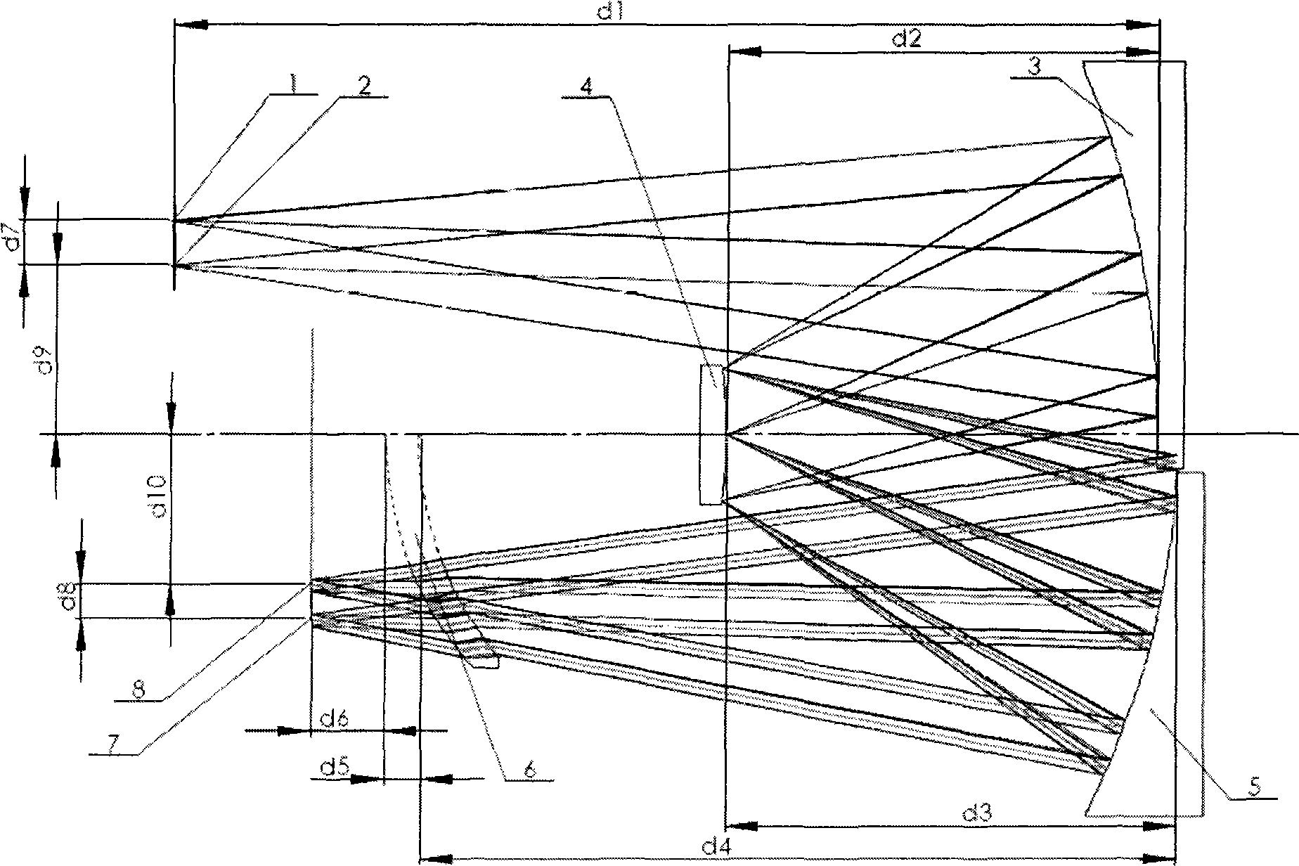
[0009] According to the optical system structure shown in accompanying drawing 1 among the present invention, we have designed a pair of slit imaging spectrometers, and the specification of spectrometers is as follows:

[0010] Working band: 1.0μm~2.5μm

[0011] System F number: F / 3.0;

[0012] Object slit length: 36mm

[0013] Spectral resolution: 312m / mm

[0014] Imaging spectrometer vertical axis magnification: 0.8.

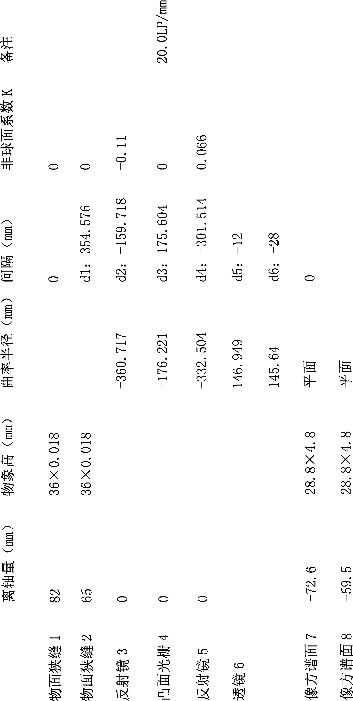
[0015] The specific structural parameters of the system are as follows:

[0016]


PUM


Abstract

The invention discloses a multi-slit high-spectrum imager carried by a satellite or an airplane for observing the ground. The system is an imaging spectrograph consisting of a convex spherical reflection grating and a secondary aspherical concave reflector, and is provided with an off-axis lens in front of an image to expand a meridian view field of an object space in the vertical slit direction, so that a flattening view field of the object space is expanded into a rectangular view field from a linear view field, then two or more slits at certain intervals are placed in the rectangular flattening view field of the object space, and the plurality of the slits form images on spectrum surfaces of different strips in an image space after passing through a spectrograph. The structure is simple; and the spectrograph can expand the image view field and reduce imaging frame frequency, and is mainly applied to spectrum imaging systems carried by the airplanes or the satellites.

Description

technical field [0001] The invention relates to an optical element and a system, in particular to a multi-slit convex grating imaging spectrometer used in an airborne or spaceborne ground observation hyperspectral imager. Background technique [0002] At present, the common convex imaging spectrometer generally adopts the OFFNER structure. A single slit is placed on the object side, and a focal plane device is placed on the image side to accept the imaging from the spatial and spectral dimensions of the slit. [0003] In the application of aerospace remote sensing, the slit of the convex grating imaging spectrometer is placed parallel to the flight direction, and the push broom flying along the track is scanned to form a three-dimensional spectral image of the ground object, and each imaging can only obtain the spectrum of one band Imaging, in the spacecraft flying at high speed, there is a problem that the imaging frame rate is too high. [0004] The sagittal field of view...

Claims


Application Information

Patent Timeline
IPC IPC(8): G01J3/36G01J3/30
Inventor 刘银年兰卫华王跃明丁学专王建宇薛永祺
Owner SHANGHAI INST OF TECHNICAL PHYSICS - CHINESE ACAD OF SCI
Learn More