Bidirectional magnetic saturated time difference fluxgate sensor

A fluxgate sensor and time difference technology, which is applied to the magnetic field measurement, the size/direction of the magnetic field and other directions using the principle of magnetic flux control, which can solve the problems of complex data processing of the fluxgate sensor, unfavorable real-time detection, and complex detection circuits. , to make up for the harsh process requirements, reduce power consumption, and achieve the effect of simple detection circuit

Inactive Publication Date: 2009-09-30
JILIN UNIV
View PDF3 Cites 35 Cited by
  • Summary
  • Abstract
  • Description
  • Claims
  • Application Information

AI Technical Summary

Problems solved by technology

At the same time, because the even-order harmonic fluxgate sensor measures the magnetic signal based on the harmonic amplitude, the corresponding detection circuit is relatively complex, including resonance, frequency-selective amplification, integral filtering, and phase-sensitive demodulator.
The existing fluxgate requires a feedback circuit to ensure the stability and linearity of the measurement, but it reduces its own resolution
The follow-up data processing of the fluxgate sensor using this principle is also relatively complicated, which is not conducive to real-time detection when high sensitivity and high precision are required.

Method used


Image

  • Bidirectional magnetic saturated time difference fluxgate sensor
  • Bidirectional magnetic saturated time difference fluxgate sensor
  • Bidirectional magnetic saturated time difference fluxgate sensor

Examples


Embodiment 1

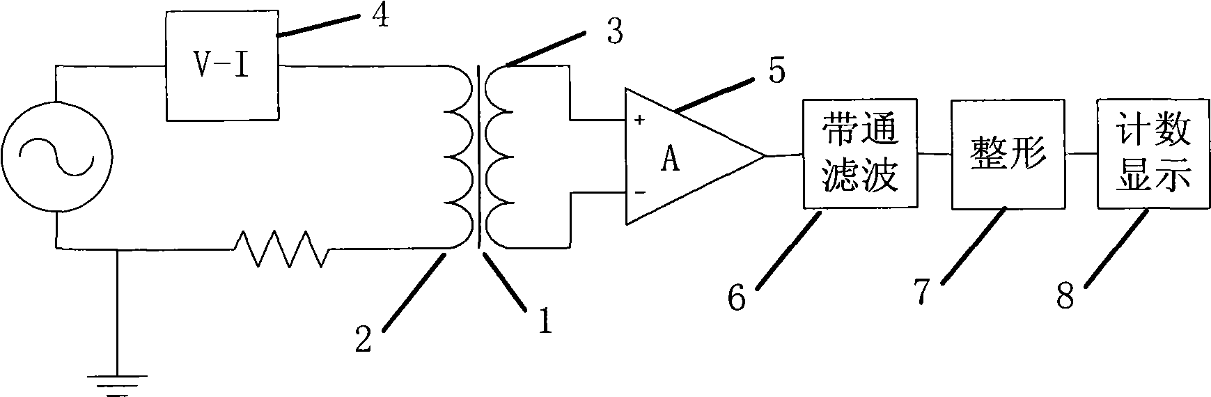
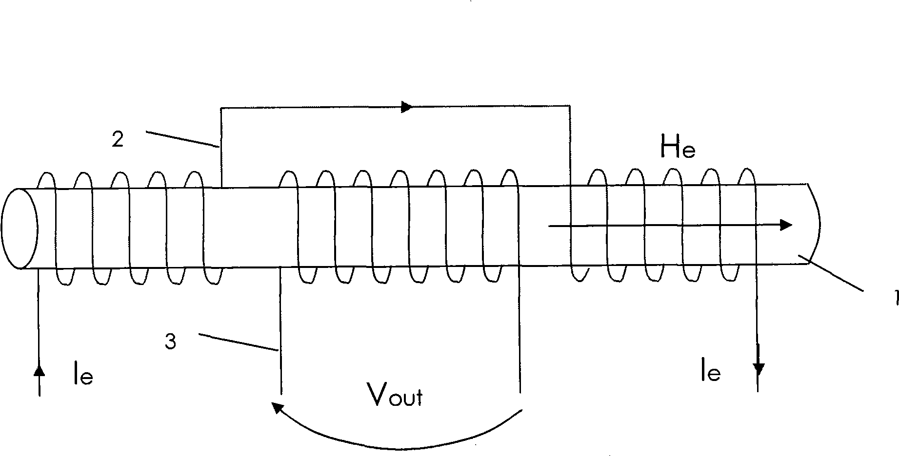
[0021] The sensor magnetic core 1 is made of nano-microcrystalline iron-based alloy to form a rod-shaped open magnetic circuit. The sensor magnetic core 1 is symmetrically pressed with a skeleton made of PCB base material, and the excitation circuit connected to the voltage-current conversion circuit 4 is alternately wound on it. The coil 2 and the induction coil 3 whose output pole is connected to the amplifier circuit 5, the output poles of the induction coil 3 are all connected to the amplifier circuit 5, and the amplifier circuit 5 is connected to the counting display circuit 8 through the band-pass filter circuit 6, the shaping circuit 7, and the period The voltage signal is converted into an excitation current by the voltage-to-current converter 4, and input to the excitation coil 2 on the sensor core 1 to generate a core excitation magnetic field, which periodically excites the sensor core 1, so that the sensor core 1 periodically reaches In the supersaturation state, wh...

Embodiment 2

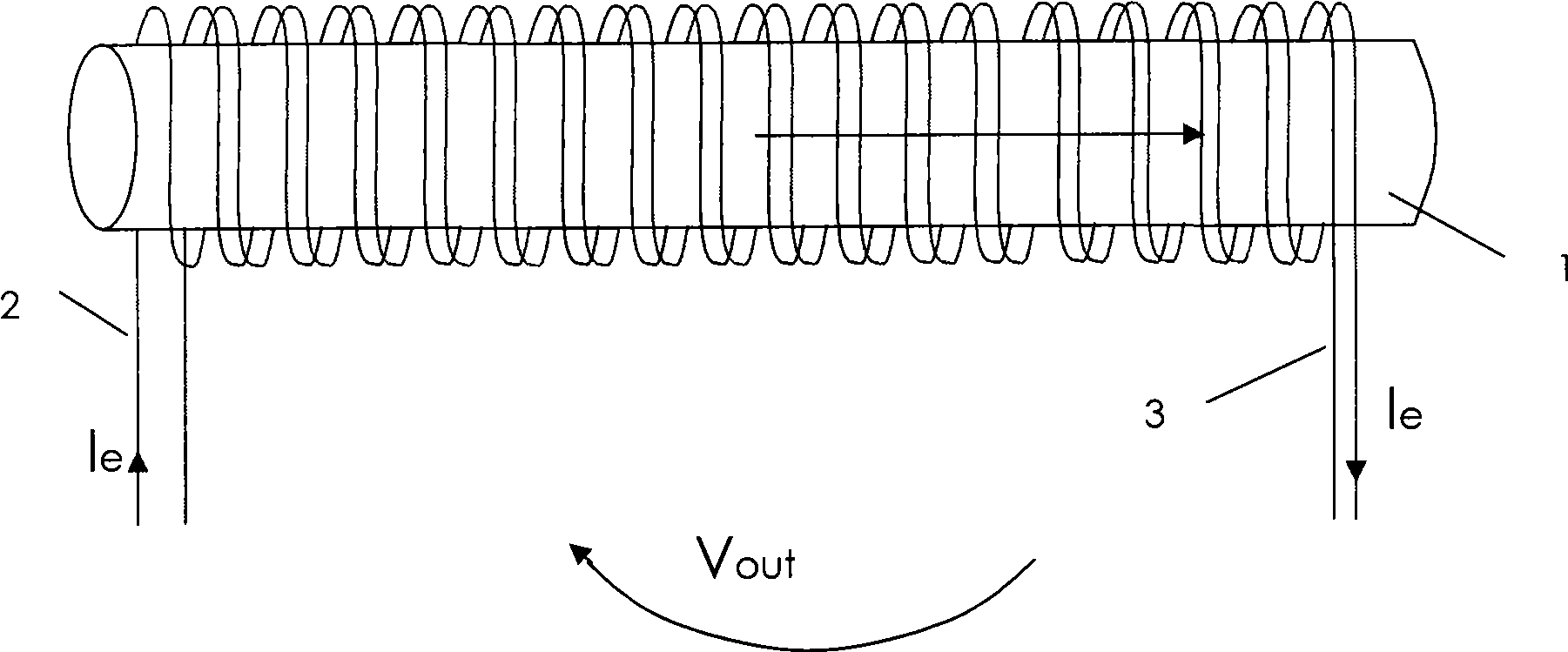
[0039] The sensor core 1 is made of iron-based amorphous alloy into a sheet structure, and the sensor core 1 is symmetrically pressed with a skeleton made of ABS plastic, and an excitation coil 2 connected to a voltage-current conversion circuit 4 is wound around the two ends of the sensor core 1. The middle section is wound with an induction coil 3, and the output poles of the induction coil 3 are connected to the amplifying circuit 5, and the amplifying circuit 5 is connected to the counting display circuit 8 through the band-pass filter circuit 6, the shaping circuit 7, and the periodic voltage signal is converted by the voltage-current converter 4 The excitation current is input to the excitation coil 2 on the sensor core 1 to generate the core excitation magnetic field, and the excitation magnetic field periodically excites the sensor core 1 to make the sensor core 1 periodically reach the supersaturation state. When the two-way magnetic saturation time difference When the...

Embodiment 3

[0042] The sensor magnetic core 1 is made of permalloy to make a closed magnetic circuit structure. The sensor magnetic core 1 is symmetrically pressed with a skeleton made of PVC material, and the two ends of the beam are wound with an excitation circuit connected to the voltage-current conversion circuit 4. The coil 2 is wound with an induction coil 3 in the middle, and the output poles of the induction coil 3 are connected to the amplifying circuit 5, and the amplifying circuit 5 is connected to the counting display circuit 8 through the band-pass filter circuit 6, the shaping circuit 7, and the periodic voltage signal is converted by voltage and current The device 4 converts the excitation current into the excitation coil 2 on the sensor core 1 to generate a magnetic core excitation magnetic field, and the excitation magnetic field periodically excites the sensor core 1 to make the sensor core 1 periodically reach an oversaturation state. When the two-way When there is a we...


PUM


Abstract

The invention discloses a bidirectional magnetic saturated time difference fluxgate sensor, which is characterized in that two ends of a sensor magnetic core are wound with exciting coils, the middle section of the sensor magnetic core is wound with induction coils, output poles of the induction coils are connected with an amplifying circuit, and the amplifying circuit is connected with a counting display circuit through a band-pass filter circuit and a retardation shaping circuit. By detecting and calculating a positive negative pulse time difference value output by the fluxgate sensor in a time domain, the strength of the measured magnetic field is judged. Compared with the prior fluxgate sensor, the detection circuit is simple, the measurement stability of the system is ensured without a feedback structure, a complex subsequent circuit is not needed, the required excitation current is lower, the data processing is simple, the measured relative quantity is little, the integral volume and power consumption of the sensor are effectively reduced, and the measurement result is acquired quickly. The fluxgate sensor avoids a filter-phase-sensitive demodulation-smooth filter circuit of the prior fluxgate sensor, makes up the defect that the prior fluxgate sensor has harsh process requirement, and achieves the digitized magnetic measurement of the fluxgate sensor.

Description

Technical field: [0001] The invention relates to a fluxgate sensor, in particular to a sensor for measuring weak magnetic field by means of two-way magnetic saturation time difference. Background technique: [0002] The application of fluxgate to measure the weak magnetic field is an important method in many existing methods of weak magnetic field measurement. The basic principle of this method is to use Faraday's electromagnetic induction phenomenon and magnetic saturation phenomenon to convert magnetic signals into electrical signals for measurement. Existing fluxgate products calculate the magnitude of the measured magnetic field by detecting the even-order harmonic amplitude of the output signal, and its sensitivity is restricted by the noise of the fluxgate probe. Generally, it is necessary to use differential probes that can suppress noise or have compensation structures. structure. Numerous existing patents are also designed based on this aspect, such as "Fluxgate S...

Claims


Application Information

Patent Timeline
Patent Type & Authority Applications(China)
IPC IPC(8): G01R33/04
Inventor 程德福卢浩王言章马波
Owner JILIN UNIV
Why Eureka
Try Eureka