Interference type double-imaging measurement device for multi-parameters of liquid crystal spatial light modulator
A spatial light modulator, imaging measurement technology, applied in optics, instruments, nonlinear optics, etc., can solve problems such as the inability to meet the requirements of multi-parameter measurement, achieve accurate acquisition, high measurement accuracy, and avoid additional errors.
- Summary
- Abstract
- Description
- Claims
- Application Information
AI Technical Summary
Problems solved by technology
Method used
Image
Examples
specific Embodiment approach 1
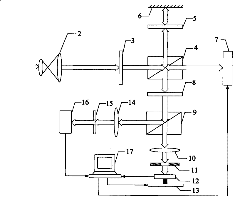
[0008] Specific implementation mode one: combine image 3 Description of this specific embodiment, a multi-parameter interferometric dual imaging measurement device of a liquid crystal spatial light modulator, which includes a beam expander 2, a polarizer 3, a first dichroic prism 4, a reflector 6, and a liquid crystal spatial light modulator 7. Analyzer 8, photodiode 12 and CCD detector 16, a multi-parameter interferometric dual imaging measuring device of a liquid crystal spatial light modulator also includes a switchable shutter 5, a second dichroic prism 9, and a first imaging lens 10 , pinhole 11, two-dimensional micro-motion stage 13, second imaging lens 14, aperture 15 and computer 17; the laser beam input by the system is incident on the beam expander 2, and after being expanded and shaped by the beam expander 2, it is incident on the polarizer device 3, after being polarized by the polarizer 3, it enters the first dichroic prism 4, and the first dichroic prism 4 divid...
specific Embodiment approach 2
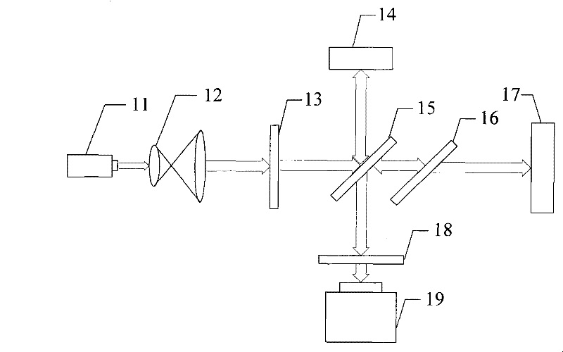
[0016] Specific implementation mode two: combination Figure 4 Describe this specific embodiment, the difference between this specific embodiment and the multi-parameter interferometric dual imaging measurement device of a liquid crystal spatial light modulator described in the first specific embodiment lies in the transmission axis of the polarizer 3 and the polarizer 8 The light transmission axes are all parallel to the liquid crystal optical axis direction of the liquid crystal spatial light modulator 7, and the switch shutter 5 can be set to an open state.
[0017] The device of this embodiment is in the interference state of two optical paths, and the polarizer 3 and the analyzer 8 are adjusted so that the light transmission axis 100 of the polarizer 3 and the light transmission axis 102 of the analyzer 8 are parallel to the liquid crystal spatial light modulator 7 in the direction of the liquid crystal optical axis 101, after the system input light beam is polarized by t...
specific Embodiment approach 3
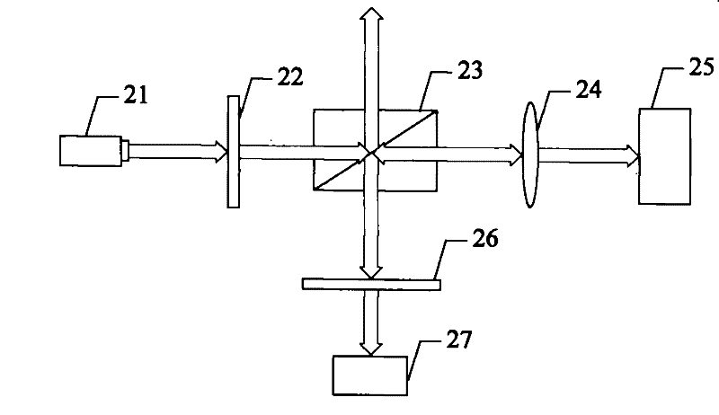
[0018] Specific implementation mode three: combination Figure 5 Describe this specific embodiment. The difference between this specific embodiment and the multi-parameter interferometric dual imaging measurement device of a liquid crystal spatial light modulator described in Embodiment 1 is that the light transmission axis of the polarizer 3 and the polarizer 8 The light transmission axes of the liquid crystal spatial light modulator 7 and the liquid crystal optical axis direction form an angle of 45°, and the switchable shutter 5 can be set to a closed state.
[0019] The device of the present embodiment is in the co-path interference state, and the polarizer 3 and the analyzer 8 are adjusted so that the polarization directions of the transmission axis 100 of the polarizer 3 and the transmission axis 102 of the analyzer 8 are consistent with the liquid crystal space light. The liquid crystal optical axis 101 of the modulator 7 forms an angle of 45°. After the system input be...
PUM
 Abstract
Description
Claims
Application Information
 - R&D
- Intellectual Property
- Life Sciences
- Materials
- Tech Scout
- Unparalleled Data Quality
- Higher Quality Content
- 60% Fewer Hallucinations
Browse by: Latest US Patents, China's latest patents, Technical Efficacy Thesaurus, Application Domain, Technology Topic, Popular Technical Reports.
© 2025 PatSnap. All rights reserved.Legal|Privacy policy|Modern Slavery Act Transparency Statement|Sitemap|About US| Contact US: help@patsnap.com


