Delay unit, annular oscillator and PLL circuit

A delay unit and delay branch technology, applied in logic circuits, electrical components, single output arrangements, etc., can solve the problems of low performance and power consumption, large phase detector gain Kvco, and poor linear performance, etc., to reduce power consumption , Improving the linear performance and ensuring the effect of phase noise performance

Active Publication Date: 2009-10-14
HUAWEI TECH CO LTD
View PDF0 Cites 16 Cited by
  • Summary
  • Abstract
  • Description
  • Claims
  • Application Information

AI Technical Summary

Problems solved by technology

[0006] The inventors found that in the implementation of the present invention, in the delay unit of the prior art, a MOS tube (Metal-Oxide-Semiconductor Field-Effect-Transistor, Metal-Oxide-Semiconductor Field-Effect-Transistor) is generally used to form a variable capacitor. Change the gate voltage of the MOS tube to change the capacitance, and since the capacitance of the MOS tube does not change linearly with the gate voltage, the linear performance of this control method is not very good
At the same time, because the capacitance of the MOS capacitor is more sensitive to the gate voltage, this makes the phase detector gain Kvco of the VCO larger, which makes it difficult to guarantee the stability of the PLL system
In addition, since the VCO load current is constant, the power consumption of the VCO at any output frequency is constant, and since its load current is actually determined by the maximum output frequency, when the output frequency is low, the performance power consumption of the prior art than very low

Method used


Image

  • Delay unit, annular oscillator and PLL circuit
  • Delay unit, annular oscillator and PLL circuit
  • Delay unit, annular oscillator and PLL circuit

Examples


Embodiment Construction

[0020] The following will clearly and completely describe the technical solutions in the embodiments of the present invention with reference to the accompanying drawings in the embodiments of the present invention. Obviously, the described embodiments are only some, not all, embodiments of the present invention. Based on the embodiments of the present invention, all other embodiments obtained by persons of ordinary skill in the art without creative efforts fall within the protection scope of the present invention.

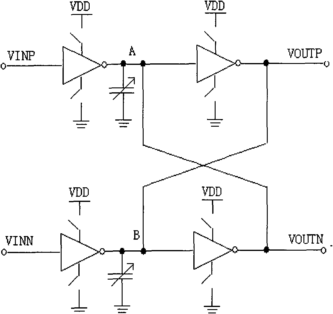
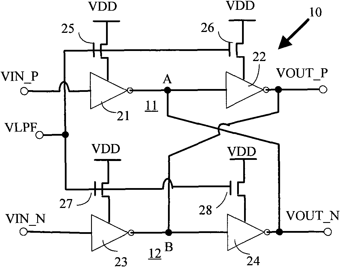
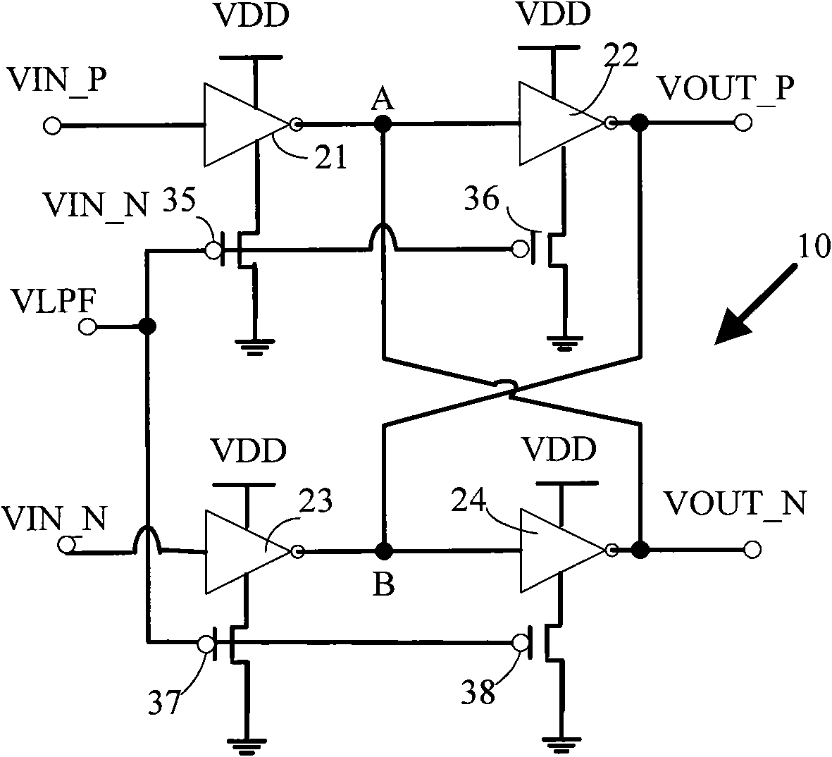
[0021] An embodiment of the present invention discloses a delay unit for a semiconductor device, including a first delay branch and a second delay branch, the first delay branch has a non-inverting input terminal for receiving a differential signal and a non-inverting output terminal for outputting a differential signal ; The second delay branch has an inverting input terminal for receiving a differential signal and an inverting output terminal for outputting a diff...


PUM


Abstract

The invention relates to a delay unit and an annular oscillator used for a semiconductor device, comprising a first delay branch and a second delay branch. The first delay branch is provided with a cophase input terminal used for receiving a differential signal and a cophase output terminal used for outputting the differential signal; the second delay branch is provided with an antiphase input terminal used for receiving the differential signal and an antiphase output terminal used for outputting the differential signal; the first delay branch and the second delay branch at least comprise an inverter and a transistor electrically connected with the inverter respectively; and the transistor receives a control signal, and the control signal is used for controlling the transistor to change the working voltage of the inverter connected with the transistor. The load resistance of the delay unit is changed with the control voltage so as to change the overturning delay of a delay unit circuit and form a symmetric structure of the delay unit simultaneously, thus guaranteeing the phase noise performance of the semiconductor devices or related circuits.

Description

technical field [0001] The invention relates to electronic devices and circuits, in particular to delay units, ring oscillators and PLL circuits of semiconductor devices. Background technique [0002] In the fields of electronics and communication, a Phase Locking Loop (PLL) uses an externally input reference signal to control the frequency and / or phase of an internal oscillation signal in the loop, and has been widely used. The core module of the PLL includes a voltage-controlled oscillator (Voltage Controlled Oscillator, VCO). The VCO structure and design directly affect the performance of the entire phase-locked loop. In today's highly integrated electronic products, low power consumption has become a necessary design index for electronic products, and the power consumption of PLL mainly comes from VCO. [0003] Because the oscillation frequency of the ring voltage-controlled oscillator is determined by the flipping delay td of each stage. The delay td of the primary d...

Claims


Application Information

Patent Timeline
Patent Type & Authority Applications(China)
IPC IPC(8): H03K5/14H03K19/0944H03L7/099H03K5/134
Inventor 肖靖帆李定
Owner HUAWEI TECH CO LTD
Why Eureka
Try Eureka