
Transducer array arrangement and operation for sodar applications

A transducer array, acoustic transducer technology, applied in the re-radiation of sound waves, instruments, measuring devices, etc., can solve the problems of uneven sound pressure, reduce the maximum intensity of sound pressure, measurement and calculation errors, etc. Uniformity and strength, the effect of improving uniformity

Inactive Publication Date: 2009-10-14
VAISALA
View PDF1 Cites 4 Cited by
  • Summary
  • Abstract
  • Description
  • Claims
  • Application Information

AI Technical Summary

Problems solved by technology

Rectangular grid spacing with circular transducers leaves 27% of the array surface blank, which creates non-uniform sound pressure across the array, potentially causing measurement errors
In addition, this inherently reduces the maximum intensity of the sound pressure, correspondingly reducing the accuracy and sensitivity of the array
Also, the use of an asymmetrical acoustic beam results in asymmetrical sensing, which creates measurement and calculation errors

Method used


Image

  • Transducer array arrangement and operation for sodar applications
  • Transducer array arrangement and operation for sodar applications
  • Transducer array arrangement and operation for sodar applications

Examples


Embodiment Construction

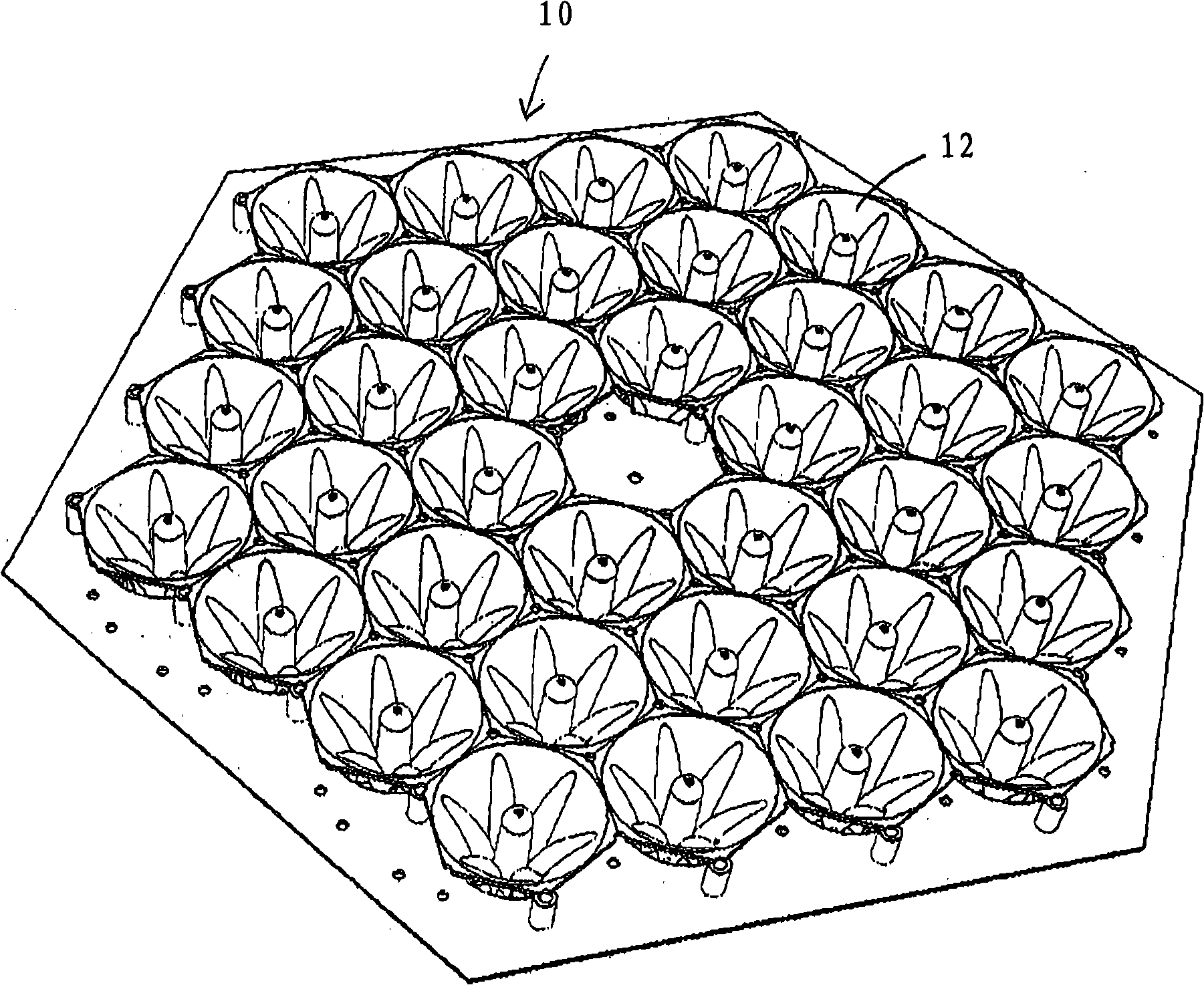
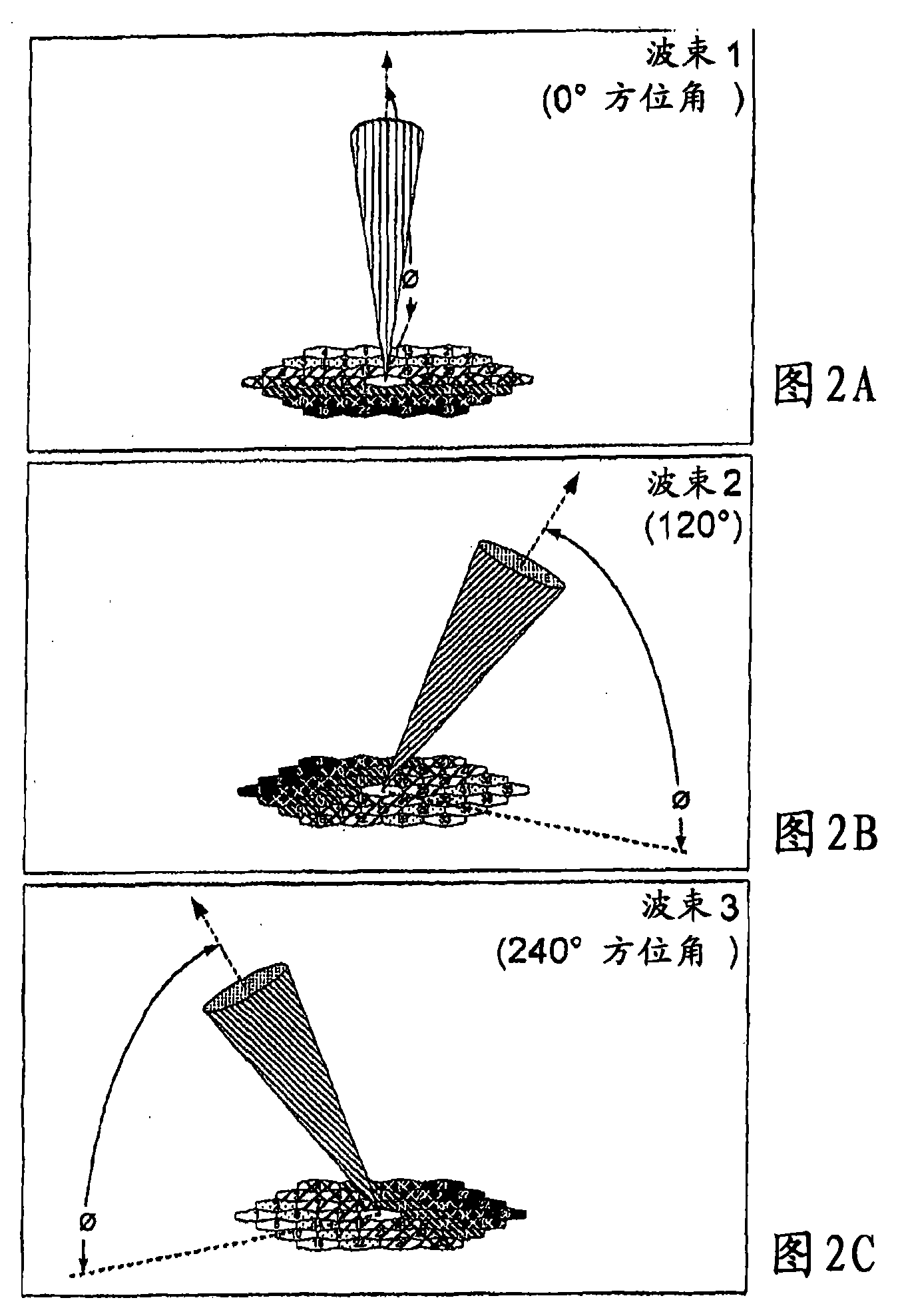
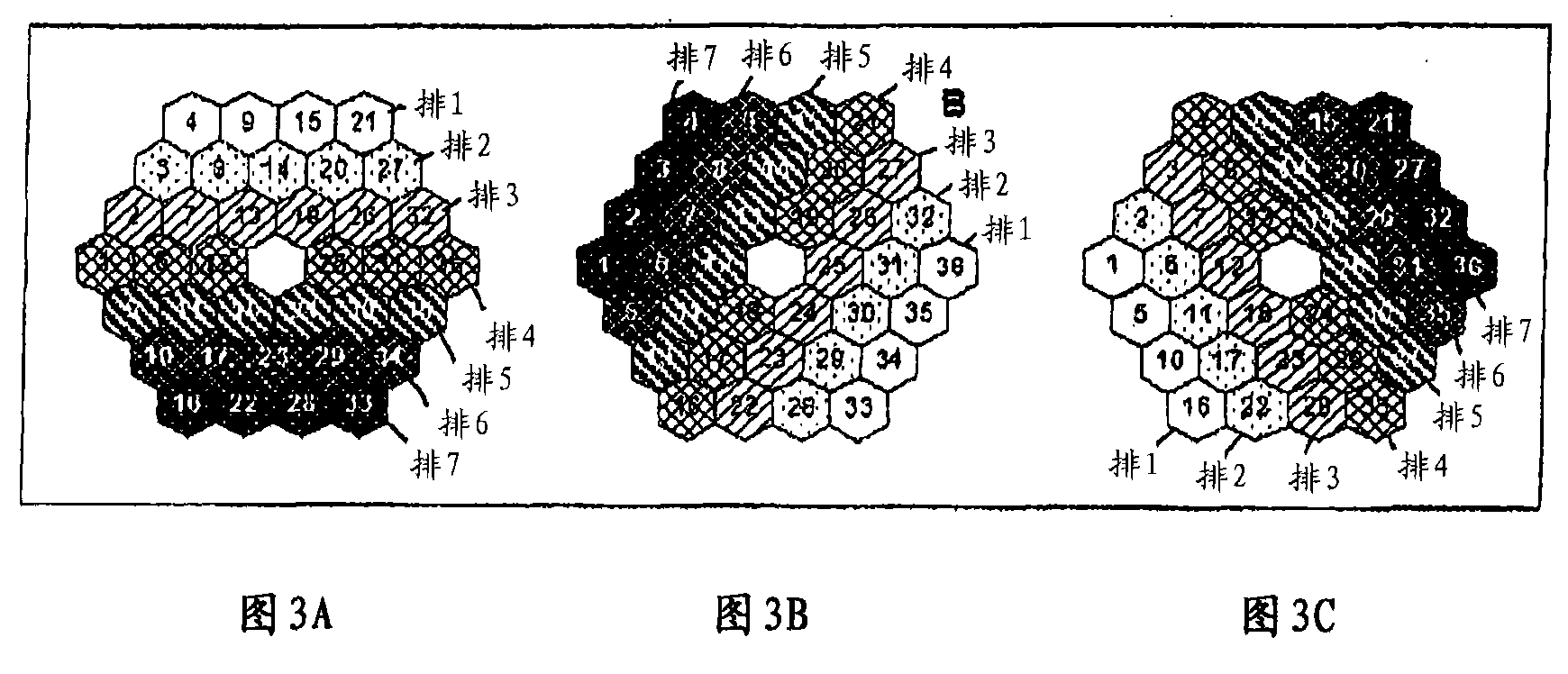
[0024] Monostatic sonar uses continuous directional acoustic beams as part of its operation. Typically, independent acoustic transducers emit sound in a wide wavefront that approximates a spherical surface, which makes these acoustic transducers unsuitable for sonar without a focusing mechanism. Such as figure 1 As shown, the array 10 of closely-filled and evenly spaced transducers can achieve focusing by generating a complex wavefront interference pattern, thereby effectively generating a main beam that is narrower than the main beam generated by a single transducer. Beam. The angular spread of the beam is related to the number of transducers in the array. Generally speaking, the more transducers, the narrower the beam produced. Arrays with 32 to 60 transducers are generally capable of generating beams narrow enough for sonar applications. The array 10 of the present invention has 36 transducers 12. Each transducer 12 has a circular actuator and horn. The transducer 12 is tightl...


PUM


Abstract

The invention discloses an array (10) of transducers (12) for a sodar system, and the operation of the array (10) in a monostatic sodar system. The array (10) is made up of a number of individual sound transducers (12). Each transducer (12) emits sound into the atmosphere and senses emitted sound that has been reflected by the atmosphere. The transducers (12) have a generally circular cross-sectional shape. The transducers (12) are arranged in a generally planar, generally hexagonal grid packing arrangement.

Description

Technical field [0001] The invention relates to a sound wave detection and ranging (sonar) system. Background technique [0002] Sonar systems use sound to detect atmospheric phenomena, such as wind speed. Monostatic acoustic radar operates by emitting directional sound pulses and detecting signals reflected from a single device. Phased array monostatic sonar uses multiple sets of acoustic transducers to transmit and receive acoustic beams in different directions with the help of electronic components. This is achieved by changing the phase of the signal emitted by the individual transducers that make up the array and changing the phase of the sampling process so that the transducer detects the signal reflected from the atmosphere. During operation, the array itself remains structurally static. This method is described in the patent number US4558594, the disclosure of which is hereby incorporated by reference. [0003] The advantages of this phased array method are: the direction...

Claims


Application Information

Patent Timeline
Patent Type & Authority Applications(China)
IPC IPC(8): G01S15/00
Inventor N·拉怀特L·曼弗雷迪W·L·萨斯
Owner VAISALA
Learn More